
leave a message
If you are interested in our products and want to know more details,please leave a message here,we will reply you as soon as we can.
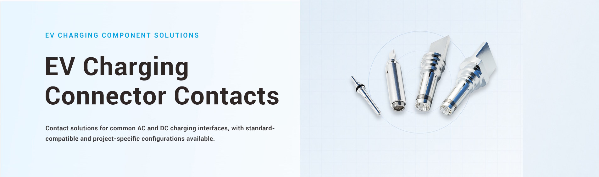
EV Charging Connector Contacts
Standalone contact pins and socket contacts for EV charging connector development and production
EV charging connector contacts provide the conductive mating interface inside an EV charging connector. Their geometry, material, surface finish, contact force and cable termination all affect how current or signals pass through the connector and how the mating parts engage.
Workersbee supplies custom contact pins and socket contacts as standalone components for EV connector manufacturers and charging-equipment OEMs. We manufacture power, protective earth and signal contacts in male and female configurations.
We support custom development from a drawing, physical sample or existing connector. Precision machining, production of contact structures, sampling and connector-level verification can be included within the same project workflow.
An EV charging connector contains several contacts with different responsibilities. Large power contacts carry the charging current. The protective earth (PE) contact provides the grounding path, while smaller signal contacts support control, proximity or communication functions according to the connector interface.
These contacts cannot be treated as scaled versions of the same component. A power contact is mainly constrained by its electrical and thermal path, whereas a signal contact may place greater emphasis on stable mating, small geometry and surface condition. The connector housing, cable conductor and mating contact also influence the final design.
|
Contact role |
Function in the connector |
Main design considerations |
|
Power contact |
Carries AC or DC charging current |
Conductive cross-section, contact resistance, temperature rise, contact force and cable termination |
|
PE contact |
Provides the protective grounding path |
Continuity, mating sequence, retention and mechanical stability |
|
Signal contact |
Supports control, proximity or communication functions |
Contact stability, dimensional fit, surface finish and mating durability |
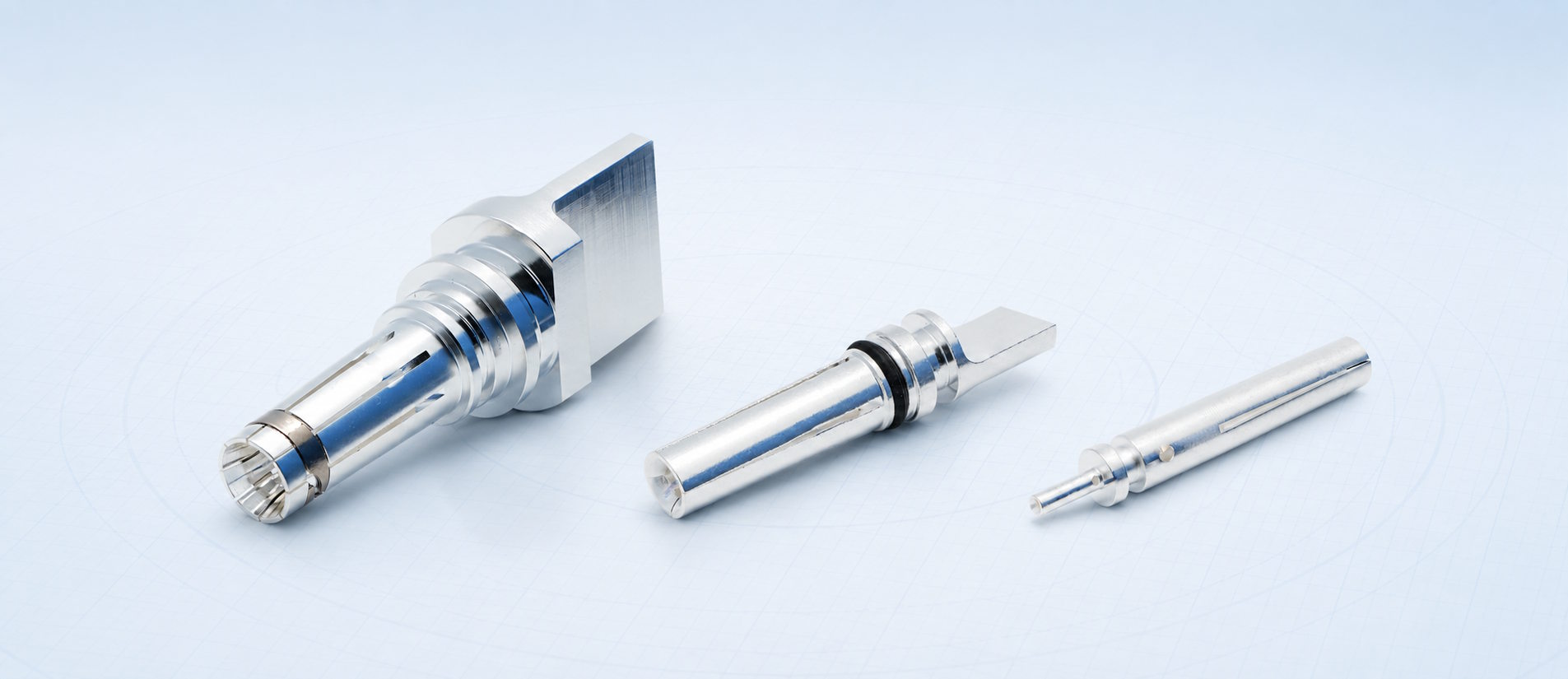
We can manufacture solid male pins, female socket contacts and smaller auxiliary contacts for these different positions. Final dimensions and functions are confirmed against the customer’s connector design and mating part.
The visible shape of a contact is only one part of its design. The mating interface determines how contact force is generated and distributed, while the rear section must connect to the conductor and fit within the connector assembly.
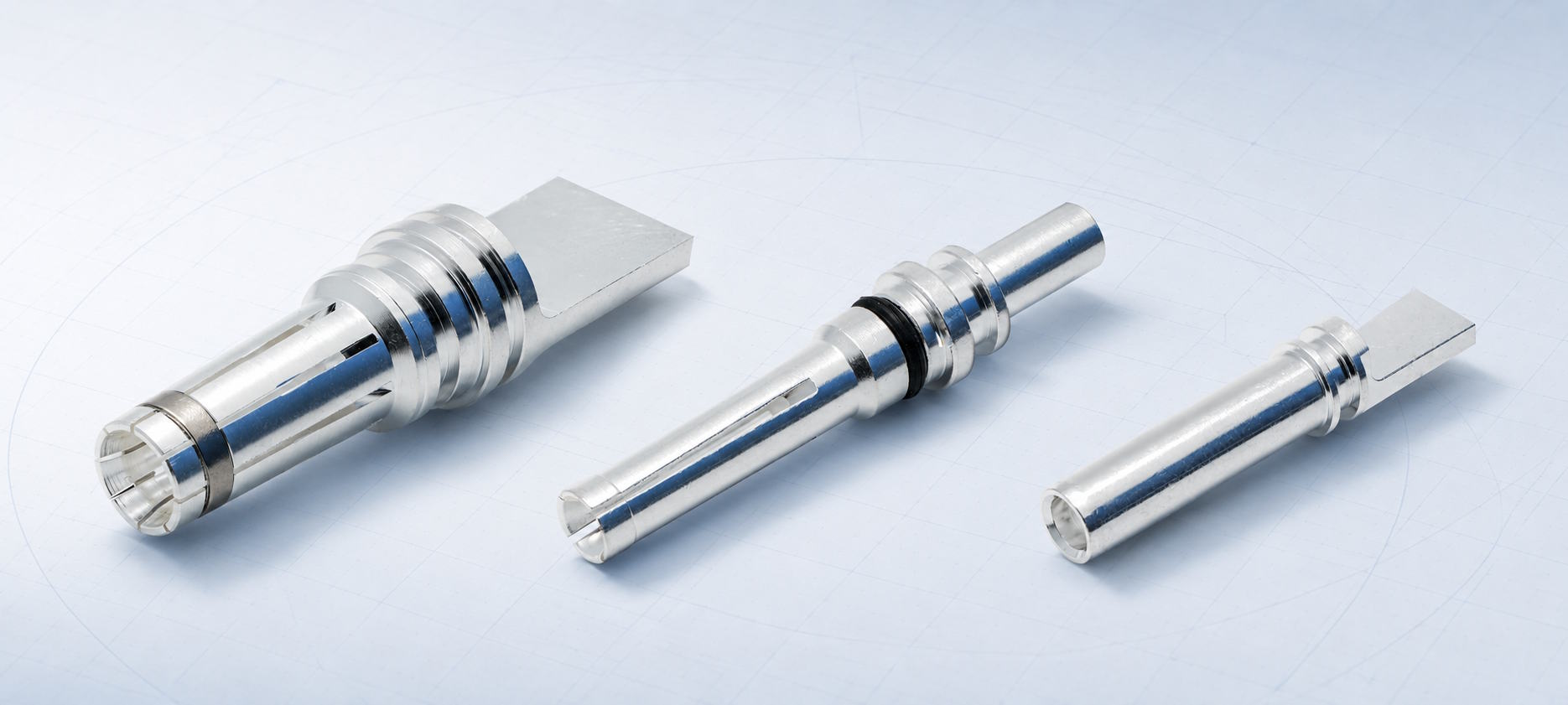
We support solid, slotted, crown-spring, lamella and hyperboloid contact structures. Contact parts for liquid-cooled connector projects can also be developed around the required connector and cooling architecture.
|
Contact design |
Basic construction |
Project factors to confirm |
|
Solid pin contact |
Machined male contact with a defined mating surface |
Diameter, effective mating length, finish, retention features and rear termination |
|
Slotted socket contact |
Female contact with elastic segments that engage the mating pin |
Slot geometry, contact force, insertion force, wall thickness and fatigue behavior |
|
Crown-spring contact |
Spring element creates multiple contact points around the mating surface |
Spring geometry, assembly method, contact force, current path and available space |
|
Lamella contact |
Multiple formed louvers provide distributed contact points |
Strip geometry, carrier design, mating diameter, force and thermal requirements |
|
Hyperboloid contact |
Angled spring wires form multiple contact lines around the mating pin |
Wire arrangement, insertion force, contact stability and assembly dimensions |
|
Liquid-cooled contact |
Contact geometry is developed as part of a cooled connector assembly |
Cooling interface, sealing, conductor connection, thermal path and connector packaging |
Crown-spring, lamella and hyperboloid structures can be produced in-house. The appropriate structure depends on the mating geometry and project conditions; it is not selected based on rated current alone.
We develop contact pins and socket contacts for Type 1, Type 2, CCS1, CCS2, GB/T and NACS connector projects. These interfaces include different combinations of AC or DC power, PE and signal contacts, so the contact set must follow the applicable connector layout and mating geometry.
CHAdeMO and MCS-related contacts can also be developed for project-specific requirements. They are handled as custom projects rather than standard contact ranges.
Interface coverage does not mean that one contact design can be transferred unchanged between standards. Even contacts with similar functions may differ in mating dimensions, retention, sealing, conductor connection and thermal conditions.
We therefore review the drawing, sample or mating connector before confirming manufacturability and the validation plan.
Current travels through the conductor termination, contact body and mating interface. Resistance at any of these points produces heat, so the design must be evaluated as a complete path rather than by base-material conductivity alone.
Contact cross-section, mating pressure, surface condition, plating, conductor connection and assembly fit can all influence contact resistance and temperature rise.
Higher-current projects may also require the contact design to accommodate the connector’s temperature-sensing or liquid-cooling architecture. These interfaces are confirmed during connector integration rather than assumed from the contact shape.
A contact must enter the mating part without excessive force while maintaining sufficient pressure after connection. Slot, spring or lamella geometry affects both insertion force and the stability of the electrical interface.
Retention features and seals must also hold the contact in the intended position inside the housing. Grooves, shoulders, O-rings and rear-end geometry are therefore functional parts of the assembly rather than cosmetic machining details.
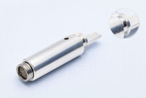
We manufacture contacts from copper and copper alloys selected according to the drawing, electrical requirements, mechanical behavior and production process.
Available plated finishes include:
· Silver-plated
· Tin-plated
· Nickel-plated
Plating is completed by external processing partners. The finish specification and inspection requirements are confirmed as part of the project documentation.
The rear of the contact must match the conductor and the connector’s assembly process. We support flat interfaces for ultrasonic welding as well as round welding ends.
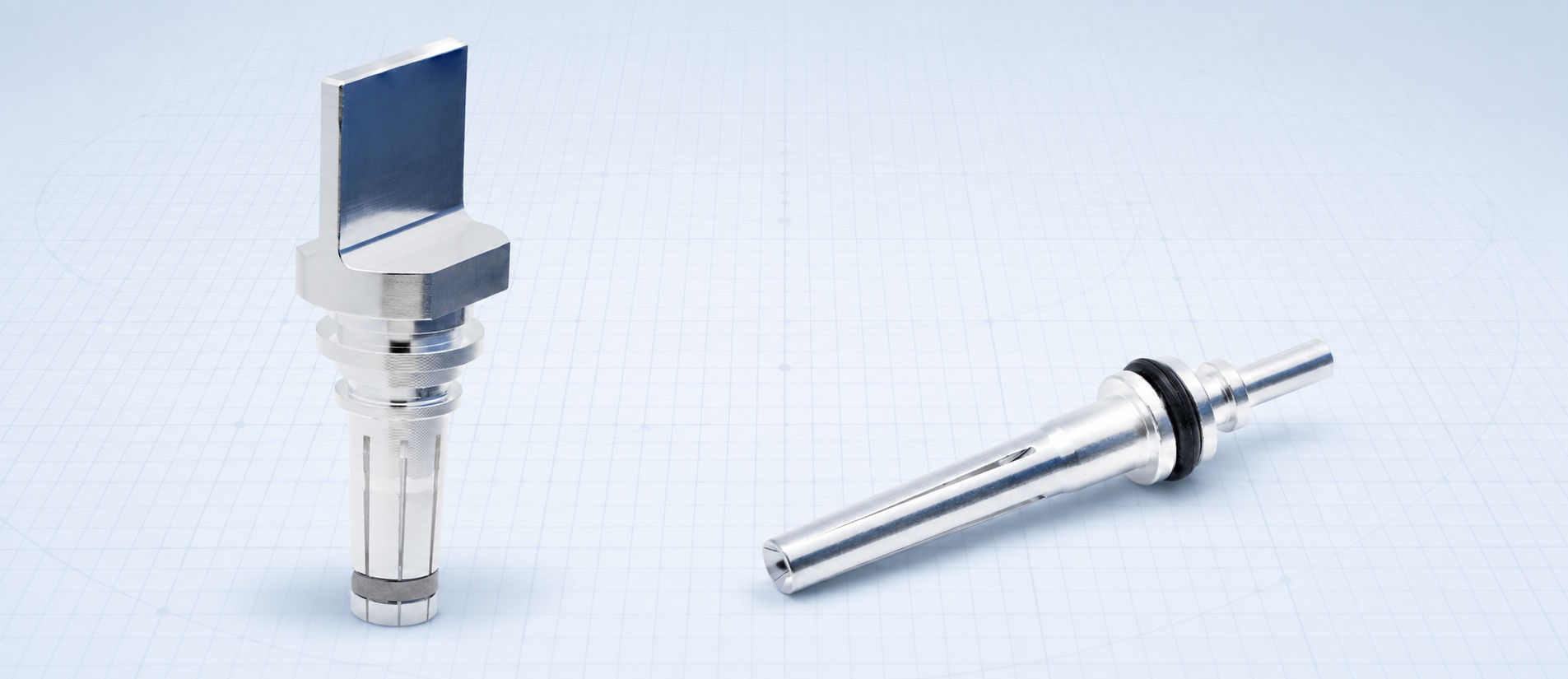
Machined shoulders, slots, sealing grooves and other assembly features can be integrated where required by the connector structure.
The termination cannot be finalized from cable size alone. Conductor construction, available assembly space, joining process, pull-out requirements and thermal path need to be considered together.
A contact project can begin with a complete drawing, a physical contact sample or an existing connector that needs a matching component.
We can also assist with contact design when the connector and mating requirements are defined but the contact drawing is not yet complete.
The normal development path is:
1. Review the available reference
We examine the drawing, sample, connector interface or mating component and identify the contact function.
2. Confirm the critical interfaces
Mating dimensions, retention, sealing, conductor connection and available assembly space are defined.
3. Align material and manufacturing decisions
The contact structure, copper or copper-alloy material, plating, machining route and secondary processes are confirmed.
4. Produce and inspect samples
Prototype contacts are checked against the agreed dimensions and assembled with the relevant connector parts when required.
5. Verify the connector interface
Electrical, mechanical and temperature-rise tests are selected according to the project before production requirements are finalized.
After sample approval, the confirmed drawing, manufacturing process and inspection requirements can be transferred to batch production.
For an initial review, customers do not need to prepare a complete validation package. A drawing, physical sample or existing connector, together with the contact function and intended conductor connection, is normally enough to begin the technical discussion.
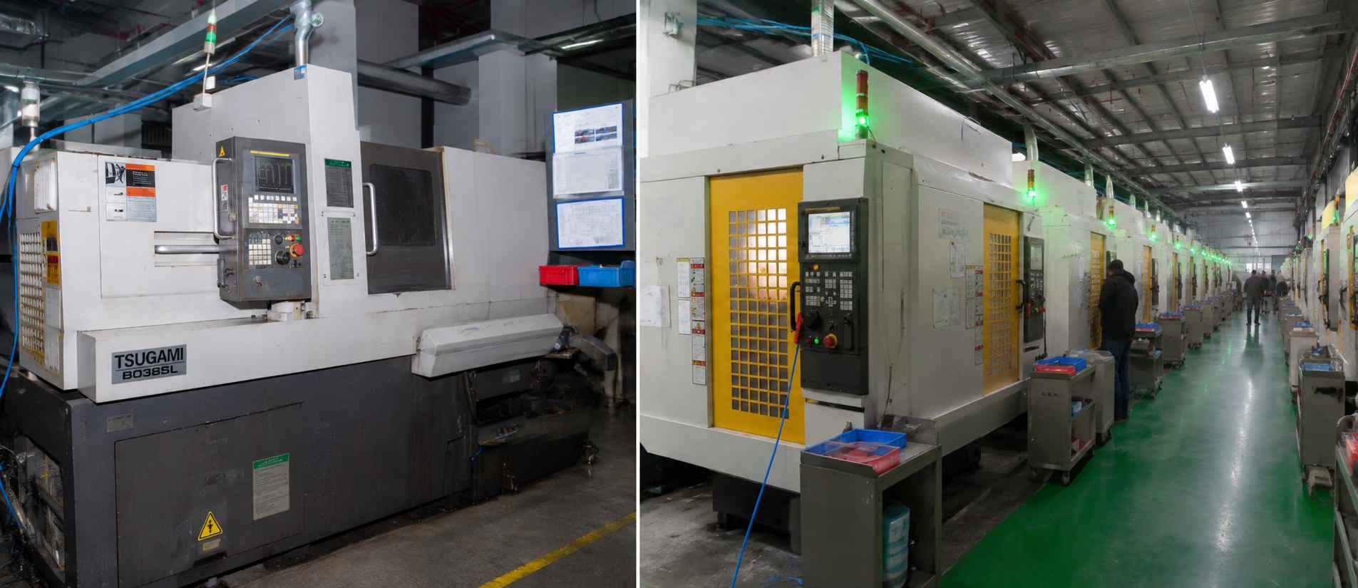
EV connector contacts often combine turned surfaces, deep internal features, grooves, slots, cross-holes and rear connection geometry in a compact part. Maintaining the relationship between these features is important for mating, sealing and assembly.
Our precision-manufacturing operation includes 66 Swiss-type CNC lathes and 27 FANUC machining centers across two manufacturing bases.
Depending on the part, turning, milling, drilling and slotting can be combined in one machining sequence, including work on the main and sub-spindles. Stamping and forming are also available for spring and lamella contact elements.
Supporting processes include:
· Deburring
· Magnetic and vibratory finishing
· Sandblasting
· Ultrasonic cleaning
· External electroplating and surface treatment
The production route is selected according to the contact geometry, sample requirements and expected volume rather than applying the same process to every component.
Workersbee operates quality management systems certified to ISO 9001 and IATF 16949. These are company-level manufacturing-system certifications. Applicable connector standards and any product-level compliance requirements still need to be reviewed for the individual project.
Part inspection begins with the dimensions and features that control assembly and mating. Depending on the drawing, this can include:
· Outer and inner diameters
· Overall length
· Grooves and shoulders
· Slots and openings
· Concentricity
· Surface condition
· Plating thickness
Our inspection resources include video measuring machines, surface roughness testers, coating thickness gauges, microscopes, and automatic dimensional inspection and sorting equipment.
Automatic inspection can be applied to features such as inner diameter and overall length when suitable for the production part.
Beyond dimensional inspection, we routinely support:
· Contact-resistance testing
· Insertion- and withdrawal-force testing
· Contact-retention testing
· Conductor pull-out testing
· Temperature-rise testing
· Connector assembly and mating-fit verification
The test combination and acceptance criteria are agreed for the specific contact and connector.
A contact can pass dimensional inspection and still require adjustment after mating or temperature-rise evaluation. Connector-level verification is therefore included when required by the project.
The most useful starting point is one of the following:
· A 2D or 3D contact drawing
· A physical contact sample
· An existing charging connector and its mating part
Please also identify the connector interface, whether the contact is used for power, PE or signaling, and how it connects to the conductor.
Target sample quantity and expected production demand help us plan the manufacturing route, but they are not required to start the first technical review.
Material grade, plating requirements, electrical conditions, mechanical force requirements, sealing details and validation criteria can then be confirmed with our engineering team as the design progresses.
Yes. A project can begin with a drawing, physical sample or existing connector. We review the mating geometry, contact function, retention, termination and assembly space before confirming the manufacturing and validation route.
Yes. We manufacture male pin contacts, female socket contacts and smaller auxiliary contacts for power, PE and signal positions.
Available structures include solid, slotted, crown-spring, lamella and hyperboloid contacts, as well as contacts developed for liquid-cooled connector projects.
Regular coverage includes Type 1, Type 2, CCS1, CCS2, GB/T and NACS. CHAdeMO and MCS-related contacts are handled as project-specific developments.
Contacts can be manufactured from copper and copper alloys according to the drawing and application. Silver-plated, tin-plated and nickel-plated finishes are available. The base material and finish requirements are confirmed for each project.
We support flat contact ends designed for ultrasonic welding and round welding ends. Other retention, sealing and assembly features can be reviewed from the connector design.
Yes. Samples can be produced for dimensional inspection, connector assembly and the agreed electrical, mechanical or temperature-rise tests before production requirements are finalized.
Yes. Once the sample is approved and the drawing, manufacturing process and inspection requirements are confirmed, the contact can move into batch production under the agreed project requirements.
We routinely support dimensional inspection, contact resistance, insertion and withdrawal force, retention force, conductor pull-out, temperature rise, and connector assembly and mating-fit verification.
The applicable methods and acceptance criteria are defined for the individual project.
leave a message
Scan To Wechat :

Scan To WhatsApp :





 English