Home

liquid cooled EV charging cable

  • AC vs DC EV charging: how it changes connector and cable design AC vs DC EV charging: how it changes connector and cable design
    Dec 02, 2025
    A home wallbox and a highway fast charger can look like the same thing from a few steps away – a plug on the end of a black cable. Underneath, they are doing very different jobs. The connector on a 7 kW AC wallbox lives a very different life from the connector on a 300 kW DC station.   The difference between AC and DC charging is not only the time it takes to fill a battery. It decides where the power electronics sit in the system, how much current runs through the contacts, how hot everything gets, and how heavy and stiff the cable has to be.   If you need a refresher on what the different charging levels mean in daily life, this overview of EV charging levels is a good starting point.     Where AC and DC sit between grid and battery On an AC charger, the grid supplies AC and the car does the heavy electrical work. The wallbox or socket delivers AC power, while the on-board charger (OBC) inside the vehicle converts it to DC for the battery. Power is capped by the OBC rating, typically somewhere between 3.7 and 22 kW for light-duty vehicles. In this arrangement, the connector and cable see moderate current and modest heat, because the hottest and most complex parts live inside the car.   On a DC fast charger, the hard work moves out of the vehicle. The cabinet converts AC from the grid into high-voltage DC and pushes that DC through the connector and cable directly to the battery bus. Power can easily sit in the 50–400 kW range or higher, so the main contacts and conductors carry much higher current and spend more time closer to their thermal limits.   In practical terms: AC keeps the toughest work inside the car, DC pushes that stress into the plug and the cable.     AC vs DC AC: power limited by the vehicle’s OBC, lower current in the cable, smaller heat load at the connector. DC: power limited by the station and battery, high current in the cable, much more heat to manage at the connector. The same vehicle can be easy on an AC plug and very demanding on a DC fast connector.     How AC and DC affect connector internals Higher voltage and current do not just change the rating on the label. They force the connector designer to make different choices in insulation, contact geometry and pin layout.   Power levels, insulation and contact design Light-duty AC charging usually runs at familiar mains-level voltages. DC fast systems sit on high-voltage battery platforms such as 400 V or 800 V. As voltage rises, the connector has to give those voltages more room. Creepage and clearance distances inside the housing get longer, insulation materials need higher performance, and the internal geometry must avoid sharp edges and dirt traps that could weaken insulation over time. The current profile changes just as much. In home and workplace AC use, connectors tend to carry tens of amps per phase. On a DC fast connector, each main contact may be asked to handle several hundred amps. That pushes designers toward larger contact faces on the DC power pins and much tighter control of contact resistance. Spring and blade systems have to keep contact force consistent over many thousands of mating cycles, because a small increase in resistance at high current can quickly turn into heat.   In practice, connector designers focus on three things: Voltage drives creepage, clearance and insulation materials. Current drives contact area, plating quality and spring design. Duty cycle (how often it is used) drives how much safety margin is built into all of the above.   Pin layout and functions Both AC and DC connectors combine power and signal pins, but they do it in different proportions. An AC connector for home or workplace use usually carries one or three line conductors, a neutral, a protective earth, and a small set of control pins for pilot signalling and proximity detection. It has enough intelligence to agree basic charging parameters and make sure the plug is seated before power flows. A DC fast connector still carries protective earth, but the main current now runs through large DC+ and DC– pins instead of lines and neutral. Around those big pins sits a richer set of low-voltage contacts. Pilot and proximity signals are still there, but high-power DC often adds communication lines and, in many designs, dedicated temperature sensing to keep an eye on the hottest parts of the connector.   Seen side by side: AC connectors carry modest power pins and a simple control pair. DC fast connectors carry very large power pins surrounded by more signal and sensing pins. As power increases, both the size of the main pins and the number of signal pins tend to grow.     Connector architectures for AC and DC Different standards solve the “AC + DC” question with different mechanical strategies.   One group of systems uses AC-only connectors. These are the inlets you see on cars that take AC at home, at work and at destination chargers. Housings are compact, handles are light, and internal layouts are straightforward. The design is tuned for comfortable daily use and a long service life at modest power.   Combo-style designs take another route. They combine an AC interface with added DC power pins in a single vehicle inlet, so one socket on the car accepts both AC and DC plugs. This reduces the number of openings that need to be cut into the bodywork and gives drivers one clear target when they walk up with a cable. The price is a larger, more complex inlet and tighter thermal design around the DC pins.   Other architectures stay away from combo inlets. Some standards keep AC and DC completely separate so each can be optimised for its own job: AC plugs stay small and light, DC plugs can become as large and robust as they need to be. Newer compact connector families push in the opposite direction and try to carry both AC and DC through a single small shell. That saves space and simplifies the interface, but it raises the bar on pin reuse, insulation design and cooling strategy.     Cables and heat: why DC looks and feels different Conductor size, weight and handling Moving a few kilowatts of AC into a car overnight does not need huge copper cross-sections. The conductors can stay moderate in size, which keeps the cable light enough to lift easily and flexible enough to coil neatly in a corner of a garage.   Moving hundreds of kilowatts of DC in a short stop is a different problem. To keep resistive losses and temperature rise under control, the conductors need far more copper. More copper means more mass, and that mass makes the cable heavier and stiffer. Extra stiffness shows up every time someone tries to bend the lead around a tight parking bay or over a kerb, and extra weight shows up at the strain-relief points where the cable enters the handle or the cabinet.   In practice: Higher DC power → thicker copper cores → heavier, stiffer cable. Heavier cable → more load on strain reliefs and terminations. AC cables can be tuned around comfort; DC cables start from thermal limits and work backwards.   AC charging cables are tuned for daily life. They are meant to be picked up with one hand, snaked between cars in a tight driveway, and coiled without a struggle when the car is done charging. DC fast charging cables have to live with a harder balance. They must carry very high current yet still bend enough that drivers of different strength and height can position the connector without feeling like they are wrestling industrial equipment. The minimum bend radius is chosen to protect the conductors and insulation, but it still needs to work with real-world layouts on charging sites.     Outer jacket, durability and liquid-cooled cables Public sites are tough on cables. Sunlight, rain, dust and road grime are routine. On top of that, leads are dropped on concrete, dragged over sharp edges and sometimes pinched or rolled over by vehicles. To survive that kind of treatment for years, DC cables tend to use thicker, tougher outer jackets. Strain reliefs are reinforced and terminations are built to absorb twisting and pulling without transferring all of that stress directly into the conductors.   Cables at home live in a gentler environment, but they still need to cope with abrasion, dirt and seasonal temperatures for the life of the charger. Their jackets can therefore lean more toward flexibility and appearance as long as basic robustness is covered.   At the top end of DC power, adding copper and relying on natural cooling eventually stops being practical. The cable would have to be so thick and heavy that many users could barely move it, and fixed supports would become mandatory at every bay. Liquid-cooled DC cables solve that by adding a cooling circuit close to the power conductors. Coolant flows near the cores, carrying heat away so the same outer diameter can move more current without runaway temperature rise. The trade-off is extra design work: the coolant path has to stay sealed and reliable for many years, leaks may need to be detected and monitored, and hoses and sensors must be routed in a way that keeps the assembly flexible enough to use.   This is why an AC cable can stay slim and soft, while very high-power DC cables tend to look thicker, more layered and, in some cases, carry visible cooling interfaces.     How to choose connectors and cables for your site Different charging sites put different weight on power, comfort, durability and cost. A small home wallbox and a bus depot may both be “EV charging projects”, but they sit in very different corners of the design space. Application Power priority Handling / comfort Durability focus Typical connector / cable traits Home AC Low to medium Very high Medium, long life in mild environment Compact plugs, slim flexible cables Destination / workplace AC Medium High Medium to high Slightly tougher housings, clear latch feedback Public DC fast charging Very high Medium Very high, outdoor abuse Larger plugs, thick or liquid-cooled cables, rugged Fleet depots / yards High to very high Medium Very high, many plug-ins per day Robust connectors, high-duty cables, easy service Home AC sites usually treat power as a low to medium priority because overnight dwell time is long. Handling comfort is very important, and durability is about lasting years in a mild environment rather than surviving constant abuse.   Drivers who are deciding between Level 1 and Level 2 at home can use our Level 1 vs Level 2 home charging guide to see how these hardware choices feel in everyday use.   Destination and workplace AC live one step up: more users, more plug-in events, more demand for solid housings and reliable latches.   Public DC fast charging pushes power to the top of the list. Handling comfort is still relevant but naturally limited by size and weight. Durability jumps to a very high priority, because the equipment must live outdoors, see many different users and tolerate occasional misuse. Fleet depots and commercial yards sit between public DC and workplace sites. Power ranges from high to very high, and connectors may be mated and unmated many times per day across multiple shifts. Contact stability, mechanical robustness and ease of service matter as much as headline power.   For a full framework on how fleets combine different charging levels across depots, homes and public sites, see our guide on what level of EV charging fleets really need.   Three simple questions usually point to the right row in the table: How long does each vehicle stay parked here? How many times per day will someone plug in and unplug? How harsh is the environment on cables and connectors over ten years?     Workersbee perspective Turning these principles into real projects means treating connector and cable choices as part of the power and site design, not as a cosmetic afterthought. The same charging level can demand very different hardware depending on environment and duty cycle.   For home, workplace and depot AC use, Workersbee develops AC connectors and charging cables built around comfortable daily handling and long-term reliability under regional standards. The focus is on predictable behaviour and a pleasant user experience within typical AC power ranges.   For public DC fast charging and high-utilisation depots, Workersbee provides DC fast charging connectors and cables engineered for high current capability, controlled contact resistance and robust mechanical performance, with options prepared for advanced cooling where project requirements call for higher power and tighter thermal margins.
    Read More
  • Can You Really Charge an EV in 10 Minutes or Less? Can You Really Charge an EV in 10 Minutes or Less?
    Nov 19, 2025
    Ten-minute charging shows up in headlines all the time, and it is hard to tell how much of that promise will ever reach real cars and real sites. If you drive an EV, the question is simple: will a quick stop really give me enough range, or am I still sitting at the charger for half an hour? If you run or plan charging sites, it turns into another version of the same doubt: does it make sense to spend more on high-power hardware for a “10-minute” experience?   For a typical EV today, the answer is clear: a full 0–100% charge in ten minutes is not realistic. What is realistic, with the right car and the right DC fast charger, cable and connector, is to add a useful block of range in that time. Understanding where that line is – and what it demands from the battery and the hardware – is what matters for both drivers and project owners.     1. Can You Charge an EV in 10 Minutes?   Charging times are always tied to a state-of-charge (SOC) window. Most fast-charging figures refer to something like 10–80%, not 0–100%. In the middle of the SOC range, lithium-ion cells can accept much higher current. Near the top, the battery management system (BMS) has to cut power to prevent overheating, lithium plating and other failure modes. That is why the last 20% often seems to crawl. So when someone claims “10-minute charging”, it usually means one of three things: ·adding a set amount of energy (for example 20–30 kWh) ·adding a set amount of range (for example 200 km) ·moving through a mid-SOC window on a specific vehicle and charger   Very few real-world combinations even try to promise a complete fill in that time.     2. How fast EVs really charge: from home AC to ultra-fast DC   In real use, charging speed is defined more by the context than by any single big kW number.   Home AC ·Level 1 and Level 2 charging at home is low power but always available. ·A car may sit plugged in for 6–10 hours overnight. ·This is enough to cover most daily driving without ever touching DC fast chargers.   Conventional DC fast charging (about 50–150 kW) ·On compatible cars, 10–80% often takes 30–60 minutes. ·Older models, small packs, or vehicles limited to lower DC power may take longer. ·For many drivers, this still fits naturally into a meal stop or shopping trip.   
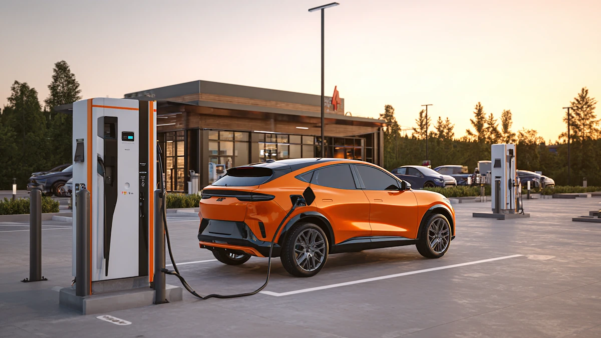
High-power and ultra-fast DC (250–350 kW and above) ·Modern high-voltage platforms can draw very high power in the mid-SOC band. ·Under good conditions – battery pre-conditioned, mild weather, low initial SOC – 10–20 minutes can move the car from a low SOC to something comfortable for the next leg.   For site operators, the same factors that shape driver experience also shape utilisation: ·arrival SOC ·battery size and DC capability of the local vehicle mix ·how long drivers actually choose to stay A site where most cars sit for 45 minutes behaves very differently, in terms of vehicles served per day, from one where most cars stay 10–15 minutes even if the advertised charger power is similar.     3. What a 10-minute stop actually adds   Drivers think in distance, not in percentages. Site owners think in vehicles per bay per day. Both can be translated from the same basic numbers. The table below uses simple archetypes to show what ten minutes on a suitable high-power DC charger might look like in practice. Vehicle archetype Battery (kWh) Max DC power (kW) Energy in 10 min (kWh)* Range added (km)* Typical use case High-voltage highway SUV 90 250–270 35–40 150–200 Long motorway legs Mid-size family sedan 70 150–200 22–28 110–160 Mixed city and highway Compact city EV 50 80–120 13–18 70–120 Mostly urban, occasional highway 
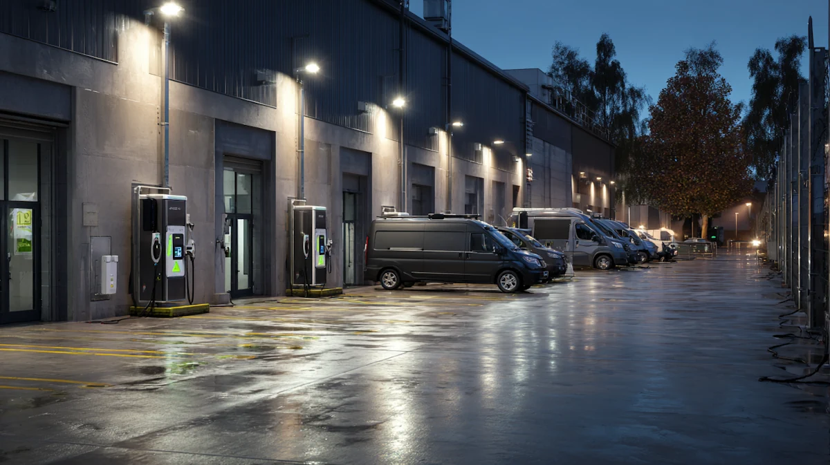
Light commercial van 75 120–150 20–25 90–140 Delivery routes, depot top-ups   *Assumes a friendly SOC window (for example 10–60%) on a compatible high-power DC charger at moderate temperature.   For a commuter, that 10-minute stop might cover several days of city driving. For a long-distance driver, it may be one more stretch of motorway without range anxiety.   Seen from a bay-turnover angle, the same table suggests that a high-power bay can serve several vehicles per hour if most drivers only need 10–15 minutes, rather than locking a bay for almost an hour per car.     4. What the battery can handle – limits and lifetime The battery is the first hard limit on ten-minute charging. Chemistry and charge rate ·Every cell design has a practical charge rate (C-rate) it can tolerate. ·Push a cell too hard and lithium can plate onto the anode, which damages capacity and can create safety issues.   Heat ·High current causes internal losses and heat. ·If heat cannot be removed quickly enough, cell temperature rises and the BMS reduces power to stay within safe limits.   SOC dependence ·Cells accept fast charging more comfortably at low and mid SOC. ·Near full, the safety margins tighten and charging must slow down.   Research into extreme fast charging works on all three fronts: new electrode materials, better cell geometry and more effective cooling paths. Even so, very fast charging is always tied to a limited SOC band and assumes a purpose-built pack and thermal system.   Lifetime and daily use For private drivers, the question is less “can the battery handle one 10-minute fast charge?” and more “what happens if I do this all the time?”   Key points: ·Occasional DC fast charging on long trips has a moderate impact on lifetime. ·Using high-power DC very frequently, especially to very high SOC, can accelerate ageing. ·Staying in a moderate SOC window and letting the BMS and thermal system do their job helps a lot.   A practical pattern looks like this: ·home or workplace AC as the backbone for daily energy ·DC fast charging when distance or time constraints demand it ·no need to avoid DC completely, but no need to chase it for every kWh either   For fleets and ride-hailing operators that live on DC fast charging, pack lifetime becomes part of the business model. Charging strategies, SOC windows and charger placement all need to be chosen with both vehicle availability and battery replacement cost in mind.     5. Hardware for 10-minute-level charging Delivering useful energy in ten minutes is not only about the car. Everything from the grid connection to the vehicle inlet has to cope with high power in a repeatable way.   The chain typically looks like this: ·Grid and transformerSufficient contracted capacity and transformer rating for multiple high-power chargers, plus any building load.   ·DC chargerPower modules sized for the intended per-bay power, with thermal design that can handle continuous high output. Intelligent power sharing across connectors when several vehicles plug into one cabinet.   ·DC cableAt hundreds of amps, a conventional air-cooled cable becomes heavy and runs hot. Liquid-cooled DC cables allow high current with manageable weight and surface temperature.   ·DC connectorThe connector has to carry that current through its contacts while keeping temperatures and contact resistance under control. It also needs to survive thousands of mating cycles, rough handling and weather, often at high ingress protection levels.   ·Vehicle inlet and batteryThe inlet must match the connector standard and current rating; the battery and BMS must actually request and accept that power.   For high-power sites, high-current CCS2, CCS1 or GB/T connectors and matched DC charging cables are central to the design, not accessories. Suppliers such as Workersbee cooperate with charger manufacturers and site owners to provide EV connectors and liquid-cooled DC cable systems that are engineered specifically for sustained high-power duty rather than occasional short bursts.     6. Planning a high-power DC site When charge-point operators or project owners consider “10-minute-style” charging, copying the highest power value from a brochure is rarely the best way to start. A more grounded approach is to work backwards from how the site will really be used.   Location and behaviour ·Highway corridors see short stays and high expectations for speed. ·Urban retail car parks and leisure destinations have natural dwell time, so medium-power DC and AC may offer better overall value. ·Depots and logistics hubs can mix overnight charging with targeted fast top-ups.   Target dwell time and vehicles per day ·Decide how long an average vehicle should stay and how many vehicles each bay should serve. ·These numbers drive the required power per bay far more than marketing claims.   Power layout ·Decide how many bays, if any, truly need 250–350 kW capability. ·Other bays may be better used at 60–120 kW, which is still “fast” for many vehicles that cannot benefit from higher power.   Cable and connector choices ·Natural-cooling DC cables are simpler and cheaper, but they limit current and can become heavy as power rises. ·Liquid-cooled cables and high-current connectors cost more but unlock shorter sessions and higher bay turnover in the right locations. ·In harsh climates or heavy commercial use, sealing, strain relief and robustness need extra attention.   Operations and safety ·High-power equipment requires regular inspection and clear procedures for dealing with contamination, damage or overheating events. ·Staff training and clear user instructions reduce misuse and extend equipment life.   Many teams find it easier to manage this complexity with a short internal checklist: main use case, target dwell time, target vehicles per bay per day, and then the charger power, cable technology and connector rating that makes sense for that combination.     7. Who benefits most from 10-minute charging Not everyone needs to be anywhere near ten-minute sessions. Long-distance private drivers ·A handful of genuine high-power bays along a corridor can transform their trips. ·They may only need to use these a few times a year, but the impact on confidence is large.   Ride-hailing, taxi and delivery fleets ·Time at the charger is time not earning money. ·For these users, even reducing a stop from 30 minutes to 15 minutes can add up across a fleet. ·However, predictable availability and smart scheduling are often more important than the absolute peak power value.   Urban commuters with home or workplace charging ·Most daily energy needs can be covered by AC. ·Occasional medium-power DC near shopping or leisure destinations is usually sufficient. ·For this group, more plugs in the right places beat a single ultra-fast unit.   From a network planning perspective, this means extreme fast charging belongs in specific corridors and hubs, not on every corner of every city.     8. How ten-minute charging might change over the next decade Several trends are likely to make fast charging feel faster, even if the ten-minute headline stays more of a special case than a daily habit. ·Higher-voltage platforms moving into mainstream price segments. ·Battery designs that can accept higher charge rates within safe windows, supported by stronger thermal management. ·Smarter site-level energy management and, in some cases, local storage to smooth grid constraints while still offering high peak power to vehicles.   For high-power projects, it makes sense to think in terms of upgrade paths: conduits, switchgear, charger footprints, cables and connectors that can be serviced and upgraded as vehicles evolve, without rebuilding the whole site.     9. What to do now: drivers, fleets and site owners For drivers: ·Do not expect a full charge in ten minutes, and do not need it for most trips. ·With the right car and charger, ten to fifteen minutes can already add a large block of range. ·Treat fast charging as one tool among several, not as the only way to power the car.   For fleets: ·Build charging plans around where vehicles actually dwell and how routes are structured. ·Use high-power DC where it clearly improves vehicle availability enough to justify the cost, and tune SOC windows to protect pack life.   For site owners and CPOs: ·Start from use cases, traffic patterns and desired dwell times, then size power, cables and connectors accordingly. ·For sites that genuinely need high-power operation, invest in high-current DC connectors and appropriate cable technology; they are core infrastructure, not optional extras.     FAQ: 10-minute EV charging Can any EV fully charge in 10 minutes today? For today’s passenger EVs, a full 0–100% charge in ten minutes is not realistic. Fast-charging times are always tied to a state-of-charge window, such as 10–80%, and assume a compatible high-power DC charger. Even the quickest cars still slow down sharply as they approach a high state of charge to protect the battery.   How much range can a typical EV add in a 10-minute stop? On a suitable high-power DC charger, many modern EVs can add roughly 70–200 km of range in ten minutes. The exact number depends on battery size, the maximum DC power the car accepts, temperature and the state of charge when you arrive. In friendly conditions, a 10-minute stop is often enough to cover several days of commuting or one more highway leg.   Does fast charging always damage an EV battery? Fast charging does add extra stress compared with gentle AC charging, especially if it is used very often and up to a very high state of charge. Modern packs, thermal systems and battery management software are designed to keep cells within safe limits and will reduce power when needed. Occasional DC fast charging on trips is usually fine; using it every day as the main charging method can accelerate ageing and is better managed with sensible state-of-charge windows.   Where does ultra-fast EV charging make the most sense? Ultra-fast DC charging is most valuable on busy highway corridors, depots and hubs where vehicles need to turn around quickly. Long-distance private drivers, ride-hailing fleets and delivery vans gain the most from shorter stops and higher bay turnover. In urban areas with long natural dwell times, a larger number of medium-power DC or AC chargers often serves drivers better than a single ultra-fast unit.   Do all high-power chargers deliver the same real-world speed? Not necessarily. The power printed on the charger cabinet is only one part of the story; the car’s own DC limit, its charging curve, the cable and connector rating, temperature and how many vehicles share the same cabinet all affect real-world speed. In practice, a well-matched car and charger running comfortably within their design limits will often give a better experience than a “bigger number” used outside its ideal conditions.     Workersbee works with charger manufacturers and site owners to design EV connectors and DC charging cables for CCS2, CCS1, GB/T and other high-power standards. When the battery, the charger, the cable and the connector are specified as one system instead of separate pieces, a ten-minute stop becomes a predictable part of the charging experience in the places where it really adds value.
    Read More
  • Workersbee 500A Liquid-Cooled EV Charging Cables: Powering the Future of Ultra-Fast Charging Workersbee 500A Liquid-Cooled EV Charging Cables: Powering the Future of Ultra-Fast Charging
    Oct 15, 2024
    In the previous article, we discussed the importance of liquid cooling technology for DC Fast Charging, which enables electric vehicles to achieve excellent charging experiences. This includes enhancing the charging power limit of High-power charger (HPC), achieving more efficient, energy-saving, and reliable charging.     Why Liquid Cooling Matters in DC Fast Charging   As EV adoption accelerates, the demand for ultra-fast, efficient, and safe charging solutions grows rapidly. Liquid cooling technology has become a critical enabler in High Power Charging (HPC), allowing systems to safely deliver 500A and beyond without overheating.   Previously, we explored the role of liquid cooling in enhancing thermal management. In this article, we'll take a closer look at the core components of liquid-cooled EV charging systems, and how Workersbee's 500A liquid-cooled CCS2 charging cables offer a competitive edge for your EV charging infrastructure.   What Is a Liquid-Cooled EV Charging Plug?   A liquid-cooled EV charging plug is engineered to manage the extreme heat generated during high-current DC charging. It consists of several essential components:   ·Coupling Part ·Enclosure ·Liquid Cooling Assembly ·Terminal Pin ·Sealing System ·Cable Clip   Spotlight: The Liquid Cooling Assembly   The core of the plug’s thermal regulation lies in the liquid cooling module, which actively disperses heat from critical contact points during high-power charging. During high-current charging, the terminal pins heat up more than the cable conductors, due to contact resistance. To mitigate this, a cooling structure is built around the pins, enabling forced liquid cooling using a circulating coolant.   The assembly is designed for:   ·Simple and efficient structure ·Easy manufacturing ·Excellent temperature rise control   Its structure typically includes:   ·Dual-sided coolant inlets/outlets (using smooth “pagoda-style” joints) ·Thermal conductive material (for heat transfer without direct coolant-metal contact) ·Fixing nuts, seals, and mounting screws   This design ensures effective cooling while maintaining electrical insulation and operational safety.     Inside the Liquid-Cooled Cable: Structure & Design Highlights   Unlike standard DC charging cables, liquid-cooled EV charging cables integrate a coolant channel within the cable itself. Here's how it works:   ·A liquid cooling tube runs through the center, carrying coolant ·The conductor wraps around the tube ·An insulated outer layer protects the system   This integrated design determines the internal layout of the plug and the cooling performance of the system.   Key Design Requirements for Public Charging Infrastructure    To ensure long-term performance, the following are essential in cable design:   1. High flexibility – Prevents cable stiffness and enhances usability. 2. Proper outer diameter – Avoids weak thin jackets while staying compact. 3. Low sheath temperature rise – Improves safety and comfort for users. 4. Strong welding – Guarantees a stable electrical connection for the pin-conductor joint.       The Role of the Liquid Cooling Tube   The cooling tube is a critical component, affecting both thermal transfer and coolant flow efficiency. Here's what matters:   ·A narrower internal channel within the cooling tube increases resistance to coolant flow, which can significantly hinder the system’s ability to remove heat effectively.     ·Outer diameter: Must balance strength, flexibility, and lightness. ·Material: Requires good chemical resistance, elasticity, and toughness.   Longer cables may generate more heat and higher resistance, so it's essential to balance cable length vs cooling efficiency.       Liquid Cooling System: How It All Circulates   Beyond the cable and plug, a complete liquid-cooled EV charging system includes:   ·Coolant pump ·Radiator/heat exchanger ·Coolant reservoir (oil tank) ·Connecting pipes     Working Principle   1. Heat generated during charging is absorbed by the coolant. 2. Once the coolant absorbs excess heat from the charging components, it flows into a heat exchanger, where thermal energy is transferred out before the liquid recirculates. 3. The coolant is returned to the reservoir and pumped back into the plug.   Advanced systems include temperature, pressure, and level sensors, enabling automatic operation with smart controls. Chargers typically only need to supply power and start signals.       Why Choose Workersbee's 500A Liquid-Cooled Charging Cable?   Workersbee's 500A CCS2 Liquid-Cooled Charging Cable is designed to deliver reliable high-power charging for demanding public and fleet applications. It has passed CE certification and uses TPU-insulated, user-friendly cables.     Core Advantages   1. Outstanding Performance Tailored cooling tube and cable designs with excellent thermal, chemical, and mechanical properties.   2. Superior User Experience Flexible and easy-to-handle cable enhances usability in public environments.   3. Maximum Safety Temperature rise of the outer jacket is strictly controlled to avoid overheating.   4. Robust Manufacturing High-quality welding of pins and rigorous production control ensure durability and long-term performance.   5. Lower Maintenance Cost Modular terminal quick-change design eliminates full plug replacement, reducing service costs.   6. Flexible Customization Options for cable length, connector type, current rating, and branded logos.   7. Global Compatibility Complies with CCS2 and international standards, ensuring wide interoperability across charging networks.     Ready for the Future of Fast Charging   As the EV market shifts toward ultra-fast public charging, liquid-cooled technology will be the foundation of safe, stable, and scalable infrastructure.   Workersbee's liquid-cooled EV charging solutions are built for the future—with innovation, flexibility, and safety in mind.   Whether you're building a highway supercharging station or upgrading your fleet depot, our 500A liquid-cooled CCS2 cables deliver the power and performance your business needs.     Reach out to the Workersbee team today for product specs, samples, or custom solutions.
    Read More

Need Help? leave a message

Leave A Message
Submit

home

products

whatsApp

contact