 CCS2 EV Connector Guide: Structure, Power, and Compatibility
Oct 13, 2025
CCS2, also known as Combo 2, is one of the main connector standards for DC fast charging in Europe and many Type 2 markets. For charging station manufacturers, CPOs, fleet operators, distributors, and EV component buyers, understanding CCS2 is not only about recognizing the plug shape. It is about knowing how connector structure, pin layout, AC/DC charging paths, power ratings, cooling methods, compatibility limits, and long-term reliability affect real charging projects.
For public charging sites, fleet depots, and high-power charging systems, CCS2 connector selection depends on more than rated current. Market fit, vehicle compatibility, thermal design, cable handling, locking reliability, certification, and maintenance planning all influence whether a connector or cable assembly is suitable for the project.
What Is a CCS2 Connector?
A CCS2 connector is built around a Type 2 AC interface with two additional DC power contacts below it. The upper section provides the Type 2 charging interface, while the lower section adds DC+ and DC- contacts for DC fast charging.
This combined structure allows a CCS2 vehicle inlet to support Type 2 AC charging and CCS2 DC fast charging when the vehicle and charging system are designed for both modes. The same physical inlet can therefore serve different charging scenarios, from AC destination charging to DC fast charging at public charging sites or fleet depots.
CCS2 is widely used in European DC fast-charging infrastructure and in many markets that follow Type 2-based charging standards. Its physical interface is associated with IEC 62196-2 for the Type 2 AC section and IEC 62196-3 for the DC charging section.
CCS2 Connector Structure and Pin Layout
The CCS2 connector has two main physical sections. The upper section follows the Type 2 layout and includes contacts used for AC charging, grounding, and control signaling. The lower section contains the two larger DC contacts used for fast charging. This layout separates power delivery from control and safety functions while allowing one vehicle inlet to support different charging modes.
The exact contact population can differ between a full CCS2 vehicle inlet and a CCS2 DC charging plug. In DC fast-charging plugs, AC power contacts may not be populated because high-power DC delivery uses the lower DC+ and DC- contacts.
Pin / Contact Area
Function
Used in AC Charging
Used in DC Charging
Practical Note
L1 / L2 / L3
AC phase conductors
Yes
No
Used for single-phase or three-phase AC charging, depending on the vehicle and supply.
N
Neutral conductor
Yes
No
Used in AC charging configurations that require neutral.
PE
Protective earth
Yes
Yes
Provides the grounding path for charging safety.
CP
Control pilot
Yes
Yes
Supports signaling between the EV and charger, including charging state and current limits.
PP
Proximity pilot
Yes
Yes
Detects plug presence and helps identify cable capability.
DC+
Positive DC power contact
No
Yes
Carries positive DC power during fast charging.
DC-
Negative DC power contact
No
Yes
Completes the DC power path during fast charging.
Pin layout is only one part of connector selection. Mechanical stability, contact quality, locking feedback, cable strain relief, and sealing performance also affect charging reliability, especially at public fast-charging sites with frequent plug-in cycles.
How CCS2 Supports AC and DC Charging
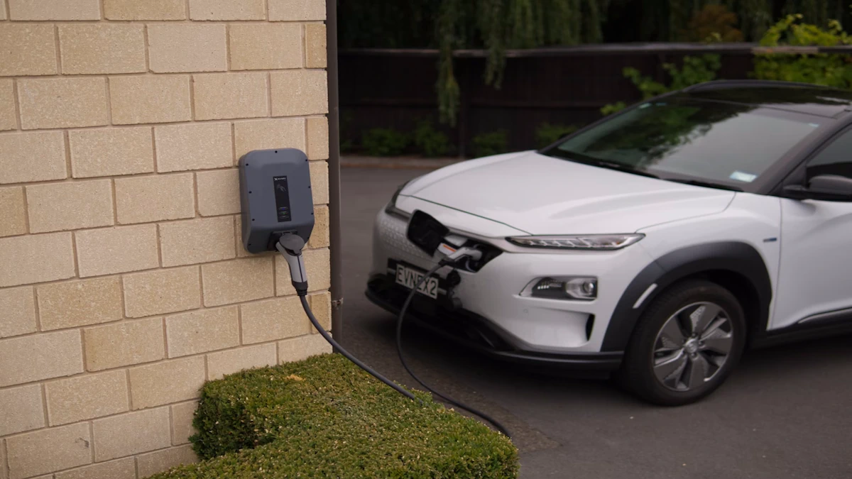
A CCS2 inlet can support AC charging and DC fast charging through separate power paths within the same combined interface. In AC charging, a Type 2 plug uses the upper section of the inlet. This is common for home charging, workplace charging, destination charging, and other long-dwell parking scenarios.
In DC fast charging, a CCS2 plug delivers high-power energy through the lower DC+ and DC- contacts. DC power is not delivered through the AC phase contacts. The upper section still supports control, proximity, grounding, and safety functions that help confirm connection status, cable capability, and charging readiness.
Physical fit should not be treated as full charging compatibility. A CCS2 inlet may accept both Type 2 AC and CCS2 DC plugs, but the vehicle and charger must support the corresponding charging mode, communication process, and safety logic.
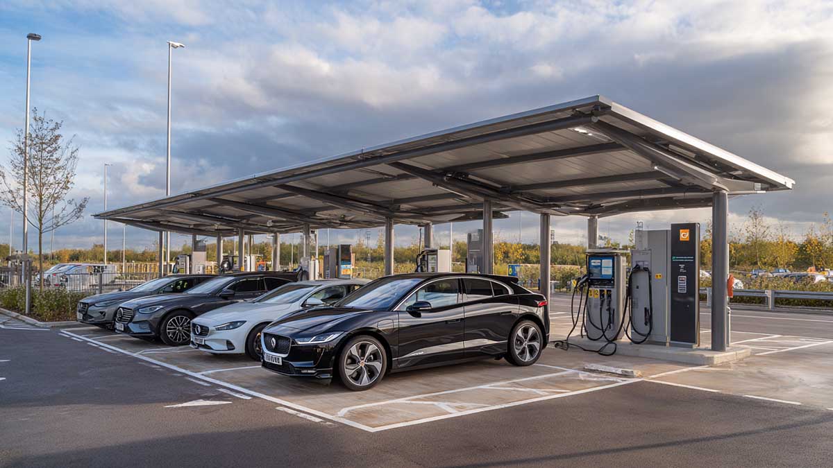
Where CCS2 Is Used
CCS2 is the main DC fast-charging connector standard in Europe and is widely used in many markets that follow Type 2-based charging infrastructure. It is also common in parts of Oceania, the Middle East, Africa, and export-oriented charging projects where European charging standards are adopted.
This regional fit matters for charging station manufacturers, distributors, and infrastructure operators. A CCS2 connector may be the right choice for a European highway charging hub, a Middle East public DC charging project, or a fleet depot using vehicles with CCS2 inlets. But it should not be treated as a universal connector for every market.
North America has historically used CCS1 for DC fast charging, while SAE J3400 / NACS is now an important connector path in that market. For global projects, connector selection should follow the target market, vehicle parc, local regulations, certification requirements, and the charging standards used by the vehicles that will actually visit the site.
CCS2 Power Rating: Voltage, Current, and Real Charging Power
CCS2 charging power is determined by voltage and current, but the rated number on a connector or charger does not mean every charging session will deliver that power. In simple terms, electrical power is calculated as voltage multiplied by current. For example, a 1000 V and 500 A system represents a theoretical 500 kW electrical ceiling.
In real charging projects, delivered power is usually lower than the theoretical maximum. It depends on the vehicle battery voltage, battery state of charge, charger cabinet output, cable current rating, ambient temperature, and the limits defined by the charging system. A vehicle may accept high power only during part of the charging curve, then reduce current as the battery approaches a higher state of charge.
Among these limits, heat is usually the most important one in high-current CCS2 applications. Contact resistance, cable design, cooling method, and plug-in frequency all affect temperature rise at the connector and cable. If the system approaches its thermal limit, the charger may reduce current to protect the connector, cable, and vehicle inlet. CCS2 selection should therefore reflect the real duty cycle and thermal margin, not only the highest advertised power rating.
Air-Cooled vs Liquid-Cooled CCS2 Connectors
Not every CCS2 fast-charging project needs a liquid-cooled connector. The choice should follow the required current level, duty cycle, ambient temperature, charging window, and maintenance capability.
Air-cooled CCS2 connectors are a practical choice for mid-power DC charging, moderate utilization, longer dwell-time parking, and cost-sensitive sites. They are simpler to install and maintain because they do not require coolant circulation, pumps, hoses, or extra cooling-system monitoring. For urban public chargers, retail parking, workplace charging, and some depot projects, air-cooled CCS2 can provide enough performance with lower system complexity.
Liquid-cooled CCS2 connectors are better suited to sustained high-current charging. Typical applications include highway fast-charging hubs, high-utilization public DC sites, fleet depots with short charging windows, hot-climate installations, and projects where derating or high handle temperature would affect uptime and user experience. Liquid cooling improves thermal control under heavier loads, but it also adds cost, system complexity, and maintenance requirements.
The decision is not “air-cooled versus better.” It is whether the site needs sustained high current under real operating conditions. If the project has frequent sessions, short dwell time, high-power vehicles, or high ambient temperature, liquid cooling may be justified. If utilization is moderate and cost control matters, air-cooled CCS2 may be the better fit.
CCS2 Connector Options for Different Charging Needs
Air-Cooled CCS2 Connector
Up to 400A
Liquid-Cooled CCS2 Connector
Up to 600A
CCS2 Connector Selection Checklist for Charging Projects
A CCS2 connector should be selected around the project, not only around the highest current rating. The checklist below helps buyers connect product specifications with real charging conditions, market requirements, and long-term operation.
Selection Point
Why It Matters
What to Confirm
Target market
Connector standards vary by region.
Confirm whether CCS2 matches the vehicles, infrastructure standard, and regulations in the destination market.
Vehicle compatibility
The vehicle inlet and charging capability define what can actually be used.
Check whether the vehicles support CCS2 DC charging, Type 2 AC charging, or both.
Charger power level
The connector must match the charger cabinet and expected site use.
Confirm charger output, power-sharing logic, and expected daily utilization.
Voltage and current rating
Power rating depends on both voltage and current, not only the advertised kW number.
Confirm voltage range, peak current, continuous current, and thermal limits.
Cooling method
Thermal design affects derating, handle temperature, and service life.
Choose air-cooled or liquid-cooled according to current level, duty cycle, and ambient temperature.
Cable length and handling
Cable reach, weight, and flexibility affect installation and user experience.
Balance parking layout, cable length, bending radius, weight, and handling comfort.
Locking and feedback
Failed lock confirmation can stop a session before charging begins.
Confirm latch design, lock feedback, microswitch logic, and charger-side signal requirements.
Sealing and protection
Outdoor chargers face rain, dust, UV exposure, and repeated handling.
Check IP rating, material durability, strain relief, and environmental suitability.
Certification
Compliance affects market access and customer acceptance.
Confirm required certifications, test reports, and documentation for the target region.
Maintenance and spare parts
CCS2 connectors are wear parts in high-use sites.
Plan inspection intervals, spare connectors, cable replacement, and failure response.
Supplier support
B2B projects often need more than a standard part number.
Confirm customization options, technical support, certification documents, spare parts, and delivery stability.
A CCS2 connector that looks suitable on a datasheet can still fail in the field if the duty cycle, thermal margin, cable handling, or maintenance plan is wrong. Selection should reflect the real charging environment, not only peak current, connector shape, or a standard part number.
CCS2 vs Type 2: What Is the Difference?
Type 2 and CCS2 are closely related, but they are not the same connector. The main difference is that Type 2 is an AC charging interface, while CCS2 adds a DC fast-charging path below the Type 2 section.
Item
Type 2
CCS2
Main use
AC charging
AC charging and DC fast charging
Connector structure
Type 2 interface only
Type 2 upper section plus two lower DC contacts
DC fast charging
Not supported
Supported if the vehicle and charger are designed for it
Typical applications
Home charging, workplace charging, destination charging
Public DC charging, highway charging hubs, fleet depots
Vehicle inlet
Type 2 inlet
CCS2 inlet
Plug compatibility
Uses a Type 2 AC plug
Can usually accept a Type 2 AC plug for AC charging and a CCS2 plug for DC charging
The key point for buyers is compatibility. A similar connector shape does not mean the same charging capability. A Type 2-only vehicle cannot use CCS2 DC fast charging unless the vehicle has the required DC charging hardware, communication support, and safety system.
CCS1 vs CCS2: Regional and Design Differences
CCS1 and CCS2 are both Combined Charging System connectors, but they are built on different AC connector bases. CCS1 uses the Type 1 / J1772 upper section, while CCS2 uses the Type 2 upper section. Both add two lower DC contacts for DC fast charging.
Item
CCS1
CCS2
AC base connector
Type 1 / J1772
Type 2
Main region
North America and related markets
Europe and many Type 2 markets
DC fast-charging contacts
Two lower DC contacts
Two lower DC contacts
AC charging support
Mainly single-phase AC
Single-phase or three-phase AC, depending on the vehicle and supply
Typical project use
North American DC fast-charging projects
European and Type 2-market DC fast-charging projects
For global charger manufacturers, distributors, and charging operators, the choice between CCS1 and CCS2 should follow the destination market and vehicle population. A connector that fits one region’s infrastructure may not match another region’s vehicles, certification requirements, or charging standard expectations.
CCS2 Compatibility Checks Before Selection
CCS2 compatibility is not only a question of connector shape. In a charging project, compatibility should be checked across the vehicle, charger, connector, cable assembly, control logic, and certification requirements. A connector may physically match the inlet but still fail to support the required charging mode, locking logic, or safety process.
Before selecting a CCS2 connector or cable assembly, buyers should confirm these points:
Compatibility Check
Why It Matters
Vehicle inlet type
Confirms whether the vehicle uses CCS2, Type 2 AC, CCS1, NACS, or another inlet design.
Charging mode
Separates AC charging, DC fast charging, and combined AC/DC use. A Type 2-only vehicle cannot gain DC fast charging through an adapter.
Communication and control
DC charging requires the correct communication process, control pilot behavior, proximity detection, and safety validation.
Locking and safety validation
The charger must confirm that the plug is inserted, locked, and ready before high power is delivered.
Certification region
CCS2 products used in different Type 2 markets may require different documentation or compliance evidence.
Adapter use
An adapter should be evaluated as a separate rated product, not as a simple mechanical bridge.
The safest approach is to define compatibility by use case, not by connector name. A public DC charger, a fleet depot charger, an AC destination charger, and an adapter-based charging scenario may all involve Type 2 or CCS2 terminology, but their technical requirements are different. Buyers should provide the target market, vehicle model or inlet type, charger output, expected current, cable length, cooling requirement, and certification needs before finalizing the connector choice.
This prevents a common project mistake: selecting a connector that matches the visible interface but does not match the charging mode, thermal load, control logic, or compliance path required in the field.
Reliability and Maintenance Checks for CCS2 Connectors
For public charging sites and fleet depots, CCS2 connector reliability is not only about passing initial tests. The connector is handled every day, exposed to outdoor conditions, and repeatedly used under electrical and mechanical stress. Over time, small changes in contact condition, locking feedback, cable strain, or sealing performance can lead to failed sessions, derating, user complaints, or earlier replacement.
Operators should pay attention to these signals during routine inspection:
Check Point
Why It Matters
What to Watch
Contact condition
Poor contact quality increases resistance and heat.
Discoloration, wear, contamination, abnormal temperature rise.
Handle temperature
High surface temperature affects safety and user experience.
Repeated hot-handle complaints or temperature-related derating.
Locking feedback
The charger must confirm the connector is properly inserted and locked.
Failed lock detection, unstable latch response, session start failure.
CP / PP signal stability
Control and proximity signals affect connection recognition and charging readiness.
Re-plug events, communication errors, unstable charging start.
Cable strain relief
Cable movement and pulling force can damage the handle and internal connections.
Cracks, loose cable entry, excessive bending, damaged sheath.
Sealing condition
Outdoor connectors face rain, dust, UV, and repeated handling.
Damaged seals, water ingress risk, dust buildup, reduced IP performance.
Derating frequency
Frequent power reduction may indicate thermal or connector-side limitations.
Current reduction under normal operating conditions.
Coolant condition
For liquid-cooled connectors, cooling performance affects high-current stability.
Leakage, low coolant level, blocked flow, abnormal pump or sensor alarms.
Maintenance planning should match site utilization. A low-use DC charger may only need periodic visual inspection and cleaning, while a high-traffic highway charger or depot system should track failed sessions, derating records, connector temperature, and replacement cycles. The goal is not only to buy a connector with the right rating, but to keep it stable under the site’s real operating load.
FAQ
What is a CCS2 connector?
A CCS2 connector, also known as Combo 2, is an EV charging connector that combines a Type 2 AC interface with two additional DC contacts for fast charging. It is widely used in Europe and many Type 2-based markets for public DC charging, fleet charging, and high-power charging projects.
Is CCS2 the same as Type 2?
No. Type 2 is mainly an AC charging interface. CCS2 uses the Type 2 upper section and adds two lower DC contacts for DC fast charging. A CCS2 inlet can usually accept a Type 2 AC plug, but a Type 2-only inlet cannot support CCS2 DC fast charging.
What is the CCS2 connector pin layout?
A full CCS2 vehicle inlet includes the Type 2 AC contact area, protective earth, control pilot, proximity pilot, and two lower DC contacts. In CCS2 DC charging plugs, the AC power contacts may not always be populated because high-power DC charging uses DC+ and DC- for power delivery.
Can a CCS2 inlet support both AC and DC charging?
Yes, if the vehicle and charging system are designed for both modes. AC charging uses the Type 2 section of the inlet, while DC fast charging uses the lower DC contacts. Physical fit alone is not enough; the vehicle must support the required charging mode, communication process, and safety logic.
Do all CCS2 chargers need liquid-cooled connectors?
No. Air-cooled CCS2 connectors can be suitable for mid-power DC charging, moderate utilization, longer dwell-time parking, and cost-sensitive sites. Liquid-cooled CCS2 connectors are more suitable for sustained high current, high-utilization sites, hot climates, and projects where derating or handle temperature is a concern.
What should buyers check before choosing a CCS2 connector?
Buyers should confirm target market, vehicle compatibility, charger output, voltage and current rating, cooling method, cable length, locking design, IP protection, certification, and maintenance plan. Supplier support, documentation, spare parts, and delivery stability also matter in B2B projects.
Selecting CCS2 Connectors for a Charging Project?
Choosing the right CCS2 connector depends on more than plug shape or rated current. Market fit, vehicle compatibility, cooling method, cable design, certification, and maintenance requirements all affect project performance.
Contact Workersbee to discuss CCS2 connector and cable assembly options for public charging sites, fleet depots, charger manufacturing projects, and high-power DC charging systems.
Read More

 Charging an Electric Car at Home: Speed, Cost, Installation, and Safety
 When a Naturally Cooled CCS1 Connector Is the Right Fit
 CCS1 Connector Selection Guide for North American DC Fast Charging Projects
 How Portable Charging Helps Commercial Fleets Reduce Range-Related Risk
 How to Start an EV Charging Business in 2026 for Commercial Sites
 Extension Cord for Portable EV Charging: Safety Checklist and Heat Test
 Precision Machining Capability: Swiss Turning, CNC Milling, Materials, and Inspection
 UK 3-Pin (BS 1363) Granny Charging: A Practical Safety Checklist for Portable EV Chargers
 Charging on Schuko (Type E/F): Safe Use for Portable EV Chargers
 CEE (IEC 60309) Red 3-Phase 16A vs 32A for Portable EV Charging
 CEE (IEC 60309) Blue 16A vs 32A for Portable EV Charging


 English


 IPv6 network supported