Home

MCS

  • How to Select EV Connectors for Fleet Charging Solutions How to Select EV Connectors for Fleet Charging Solutions
    Sep 03, 2025
    If you manage an EV depot, EV connectors for fleet charging are not just plug shapes. They affect uptime, safety, driver workflow, and total cost. The common options you will meet are: ·CCS1 or CCS2 for DC fast charging ·J3400 also called NACS in North America ·Type 1 and Type 2 for AC charging ·MCS for future heavy trucks     Quick glossary AC vs DC: AC is slower and works well for long dwell times at the depot. DC is faster for quick turnarounds. CCS: Combined Charging System. Adds two big DC pins to a Type 1 or Type 2 style for fast charging. J3400: The SAE standard based on the NACS connector. Compact handle, now adopted by many new vehicles in North America. Type 1 and Type 2: AC connectors. Type 1 is common in North America. Type 2 is common in Europe. MCS: Megawatt Charging System for heavy trucks and buses that need very high power.     A simple five-step framework   
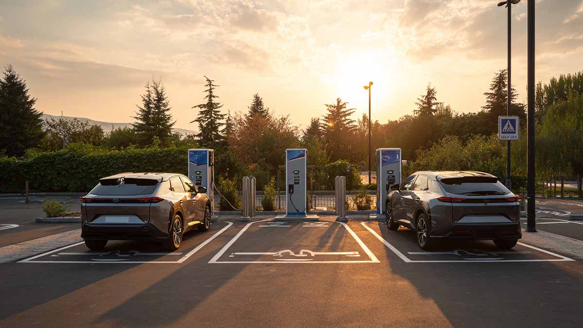
1. Map your vehicles and portsWrite down how many vehicles you have by make and model, and what ports they use today. In North America that often means a mix of CCS and J3400 during the transition. In Europe you will see CCS2 and Type 2. For mixed ports, plan to support both on key bays instead of relying on adapters every day.   2. Decide where charging happens Depot first: Choose AC for overnight or long dwell and use DC on a few lanes for peak demand. On-route: Prioritize the dominant port in your region so drivers can plug in without confusion. Tip: In mixed fleets, dual-lead posts that offer CCS and J3400 on the same dispenser reduce idle time.   3. Size power and cooling the practical wayThink in current, not only kilowatts. The higher the sustained current, the hotter the cable and handle get. Natural cooling: simpler service and lower weight, good for many depots and moderate current. Liquid cooling: for high throughput lanes, hot climates, or heavy use where sustained current is high.   4. Make it easy for drivers and techsCold sites can make cables stiff. Hot sites raise handle temperatures. Choose handles that are glove-friendly, with good strain relief, and add cable management like booms or retractors. This cuts drops and damage, which are common causes of downtime.   5. Confirm protocols and policy fit OCPP 2.0.1 support enables smart charging and depot load management. With ISO 15118, Plug & Charge uses secure certificates to handle sign-in and billing in the background, no cards or apps needed. If you depend on public corridor funding in the US, make sure the connector set stays compliant as rules evolve.     Connector choices by situation Situation Recommended connector setup Why it works Notes North America, light-duty fleet with mixed ports Dual-lead posts offering CCS and J3400 on high-use bays; AC Type 1 at base Covers both port types while keeping AC costs low Limit daily reliance on adapters Europe depot with vans CCS2 for DC lanes, Type 2 for AC rows Matches current market and vehicles Keep spare handles and seals Hot climate, fast turnarounds Liquid-cooled DC handles on express lanes Keeps handle temperatures in check at high current Add cable retractors Cold climate, long dwell Mostly AC with a few DC posts; naturally cooled DC handles AC suits long dwell, natural cooling is simpler Choose jacket materials rated for cold Medium-duty trucks now, heavy trucks coming Start with CCS posts but pre-wire and plan bays for MCS Avoids future tear-outs Reserve space for larger cables and clear approach paths     What to pick today if your fleet is mixed Put dual-lead CCS plus J3400 on the busiest lanes so any car can charge without waiting. Standardize signage and on-screen prompts so drivers always grab the correct lead. Use AC where vehicles sleep and DC only where the schedule is tight. Keep a few certified adapters as contingency, but do not build daily operations on adapters.     Operations and maintenance made simple Stock spares for high-wear parts: latches, seals, dust caps. Document the tools and torque values your techs need. Train drivers on proper holster use to keep water and dust out of the connector. Choose naturally cooled handles where your sustained current allows. Use liquid-cooled only where the duty truly needs it.     Compliance, safety, and user experience Check local codes and accessibility. Ensure a comfortable reach to holsters and clear floor space. Label dual-lead dispensers clearly so drivers pick the right connector the first time. Align your software stack with OCPP 2.0.1 and your future plan for ISO 15118 to support smart charging and Plug and Charge as vehicles allow.     Printable checklist List every vehicle model and its connector type Mark depot vs on-route charging for each route Decide AC or DC for each bay based on dwell time Pick natural or liquid cooling based on sustained current and climate Add cable management: booms or retractors where traffic is heavy Confirm protocols: OCPP 2.0.1 now, plan for ISO 15118 Stock spare latches, seals, and one extra handle per X lanes For heavy trucks, reserve space and conduit for MCS     A short example You run 60 vans and 20 pool cars in a US city. Half of the new cars arrive with J3400, while older vans are CCS. Most vehicles sleep at the depot. Install AC rows for vans that return every evening. Add four DC posts with dual leads CCS plus J3400 for vehicles that must turn quickly. Choose naturally cooled handles on most DC posts to simplify field service. Use liquid-cooled only on two high-throughput lanes that serve peak demand at shift change. Pre-plan space and conduit for future medium trucks and, later, MCS.     Where Workersbee fits For depots that value simpler maintenance, a high-current naturally cooled CCS2 handle can reduce weight and service complexity. For hot sites or very high throughput, specify a liquid-cooled CCS2 handle on the express lanes. In Europe, align with CCS2 and Type 2 across AC and DC. In North America during the transition, cover CCS and J3400 on the busiest bays.
    Read More
  • 2025 Megawatt Charging System (MCS) Guide for Heavy-Duty EVs 2025 Megawatt Charging System (MCS) Guide for Heavy-Duty EVs
    Sep 01, 2025
    What MCS isMCS is a high-power DC charging system for heavy-duty EVs such as long-haul trucks and coaches. Current industry targets reference a voltage window up to ~1,250 V and current up to ~3,000 A, enabling multi-megawatt peak power. Early pilots have already shown 1 MW sessions on prototype long-haul trucks.     Why the industry needs it nowDriver-hours rules create natural charging windows: in the EU, a 45-minute break is required after 4.5 hours of driving; in the U.S., a 30-minute break is required after 8 hours of driving. The practical goal for MCS is to turn those mandated stops into meaningful refueling events without breaking route plans or depot schedules.     How it works Power math. Power = Voltage × Current. At 1 MW, 30 minutes of charging delivers about 500 kWh (gross). Battery window. A long-haul pack in market today is often ~540–600+ kWh installed. A 20–80% top-up on a 600 kWh usable pack equals ~360 kWh—well within what a 1 MW stop can deliver in half an hour when thermal limits and charge curves allow. Real-world energy use. Heavy-duty e-trucks publicly tested at ~1.1 kWh/km (~1.77 kWh/mi). If ~460 kWh actually reaches the battery (illustrative ~92% DC-to-pack efficiency), a stop can recover roughly ~420 km (~260 mi) of range under favorable conditions. Hardware & thermal. High current requires liquid-cooled cables and embedded temperature sensing (e.g., PT1000-class RTDs in the cable/contacts) so the handle stays safe and manageable for repeated manual use. Communication. High-level vehicle–charger messaging authenticates the session, negotiates power, and carries metering and status data over higher-bandwidth links suited to fleet operations.     Standards and interoperabilityStandards programs for the system (requirements), EVSE, connector & inlet, vehicle behavior, and communications are moving in step so trucks and chargers from different brands work together at scale. System-level guidance and connector definitions now align with public pilots and lab testing; additional revisions are expected as field data grows.     Milestones and progress 1 MW pilot charging publicly demonstrated on a prototype long-haul e-truck (2024). Heavy-duty models publicly list MCS-class charge windows such as 20–80% in ~30 minutes as a design target for near-term rollouts. Connector/inlet test programs instrument couplers with multi-point thermocouples to validate temperature rise and duty cycles at very high current.     Where MCS lands first Freight corridors where a 30–45-minute stop must add hundreds of kilometers of range Intercity coach hubs with tight turnarounds Ports/logistics terminals with high daily energy throughput Mines/construction and other duty cycles that cycle large packs continuously     What makes MCS different from car fast charging Scale & duty cycle. Daily high-energy operations vs. occasional road-trip stops. Connector & cooling. Couplers for very high currents employ liquid cooling and ergonomics that support frequent, safe hand connects and disconnects.. Ergonomics. Inlet position and handle design account for large-vehicle geometry and future automation.     Planning the site and the grid (worked examples)   Capacity & topology Example A (four bays): If you plan 4×1 MW dispensers but expect ~0.6 simultaneity and 30-minute average dwell, diversified peak ~2.4 MW and nameplate peak 4 MW. Choose a transformer in the ~5 MVA class to leave headroom for auxiliaries and growth. Ramp rates at megawatt levels are steep; DC bus or modular cabinet architectures help route power where it’s needed without oversizing every bay.   Storage & load management A 1 MWh on-site battery can shave ~1 MW for one hour. In the four-bay example, storage can trim the grid tie from ~4 MW toward ~2.5–3 MW during overlapping 30-minute peaks, depending on control strategy. Smart power management smooths current ramps, pre-conditions packs, and prioritizes imminent departures.   Civil, thermal, environmental Shield coolant hoses and cable pathways, and reserve clear maintenance access around pumps and heat exchangers. Specify ingress protection for dust, moisture, and road grime; plan ventilation for enclosures. Use quick-swap subassemblies (handles, cable sections, seals, sensors) to keep uptime high.   Operations & uptime Track both charger-side and vehicle-side fault codes; align spares & SLAs with route commitments. Make interoperability tests part of commissioning; early fixes are months of uptime gained.     Safety & compliance highlights Lockout, leakage/insulation monitoring, emergency-stop chains, and short-circuit energy handling are part of the spec family. Thermal limits and temperature sensing in cables/connectors keep surface temperatures and contact temperatures within safe bounds for repeated use. Ergonomic placement and handle geometry keep manual coupling practical at scale.     Procurement & rollout checklist Vehicle compatibility: inlet location, voltage window, current limits, communication profiles supported now and via firmware Power strategy: dispensers now, maximum per site later, and how cabinets/power blocks can be reconfigured Cooling & service: coolant type, service intervals, field-replaceable modules Cyber & billing: authentication methods, tariff options, secure update paths, metering class     Commissioning & QA: interop with target trucks, thermal & current-ramp tests, baseline KPIs (utilization, session efficiency, station availability)     FAQHow fast is it in practicePublic pilots at ~1 MW have shown ~20–80% in about 30 minutes on long-haul prototypes, with actual time governed by pack size, temperature, and the vehicle’s charge curve. Will passenger cars use MCSNo. MCS is tailored to heavy vehicles; cars continue with connectors and power levels optimized for smaller packs. Is liquid cooling requiredFor hand-held cables at very high current, liquid cooling is the practical way to keep temperature and weight within safe limits. What about the standards timelineSystem, EVSE, coupler, vehicle-side, and communications documents are being published/updated in coordination with field experience and interop events; further revisions are expected as deployments grow.     Workersbee and MCSWorkersbee is a connector-focused R&D and manufacturing partner. We have initiated development of a reliable MCS connector engineered for high-current, liquid-cooled operation, ergonomic handling, and maintainability. Prototyping and validation are underway, with a targeted market launch in 2026.
    Read More

Need Help? leave a message

Leave A Message
Submit

home

products

whatsApp

contact