 What Are the Best Home Charging Solutions for EV Owners
Dec 17, 2025
A lot of EV owners start with the same assumption: if you are installing home charging, you must go straight to the biggest amperage available. In reality, the best home setup is the one that quietly fits your driving, your panel, and your future plans.
There are five home charging paths people actually choose from. A standard Level 2 wallbox for one EV. A Level 2 wallbox with dynamic load management for tight panels. A shared-power setup for two EVs. A portable Level 2 unit for rentals or multi-locations. And Level 1 charging that stays perfectly valid for some households.
Quick pick: choose the right home charging setup in 30 seconds
If you drive about 15–30 miles a day and your car sits at home for 10–12 hours most nights, Level 1 can be enough.
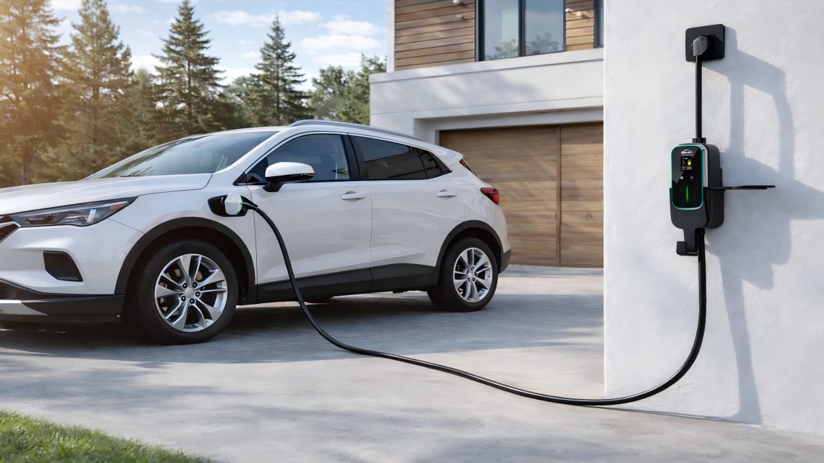
If you have one EV and a typical 100–200A panel, a standard Level 2 wallbox at 32–40A is the common “set it and forget it” choice.
If your home has a 100A panel or lots of electric appliances, pick Level 2 with dynamic load management so charging automatically backs off when the house load rises.
If you have two EVs (now or soon), choose power sharing, linked wallboxes, or a true dual-output unit so the system manages current for you overnight.
If you rent or charge in more than one place, a portable Level 2 unit can cover home use and travel without a fixed install.
If your charger will live outdoors, prioritize weather rating, sealing, and a cable that stays flexible in cold weather over chasing the highest amps.
Do you really need Level 2 at home, or is Level 1 enough?
Start with your daily miles and your overnight parking time. Those two numbers decide whether Level 1 can keep up. If you drive 15 to 30 miles a day and park at home for 10 to 12 hours, Level 1 often works fine. It adds miles slowly, but the battery refills while you sleep. If your daily driving is higher, or you do back-to-back trips, Level 2 becomes a big quality-of-life upgrade. It does not just charge faster. It closes your energy gap even on busy days, so you do not have to think about it.
A simple rule helps. If Level 1 can replace what you drive in a normal night, you do not need Level 2 for speed. You might still want Level 2 for convenience, colder climates, or future needs, but it is not a must.
Find your row: which home setup fits your household?
Before going deep on specs, match your home to the right solution type. The table below is a quick map. Find the row that looks like your household, then use it to guide your choices in the next sections.
Household scenario × recommended solution
Household scenario
Typical conditions
Best-fit solution type
Core recommendation
First EV, single-car home
Garage or driveway, 100–200A panel
Standard Level 2 wallbox
40A continuous is the common sweet spot
Budget upgrade from Level 1
Panel OK, want simple install
Plug-in Level 2
32–40A, correct outlet and wiring
100A panel, many appliances
Limited spare capacity
Level 2 with dynamic load management
Keep charging safe without service upgrade
Two EVs now or soon
One charger nightly feels tight
Shared-power or linked Level 2
Power sharing beats brute amps
Apartment or rental
No fixed wallbox install
Portable Level 2
Flexible and take-with-you
Outdoor, cold, humid, coastal
Weather exposure
Outdoor-ready Level 2
Cable feel and sealing matter more
Solar or time-of-use rates
Want cost optimization
Smart Level 2
Scheduling and surplus solar charging
If you land on the first row, your choices are straightforward. If you land on the panel-tight or two-EV rows, the next sections will matter a lot.
Can your panel handle Level 2? Two ways to avoid a costly upgrade
Many homes can add Level 2 charging with no drama. Others are tight on capacity, especially older houses with 100A service and electric HVAC, dryers, ovens, or hot tubs. The important point is this: a tight panel does not automatically mean no Level 2. It usually means you need one of two approaches.
Path A is dynamic load management at the charger. The charger monitors the home load through current sensors and automatically reduces charging when the house is drawing close to the panel limit. When appliances cycle off, charging ramps up again. You keep Level 2 convenience without a panel upgrade.
Path B is time-sharing or shared-power charging. You schedule charging to run when the home load is low, usually overnight. In two-EV homes, a shared-power system splits current between cars or alternates charging. The house never sees a risky peak.
If your panel is 200A and you run one EV, you may never need these features. If your panel is 100A, or you are adding a second EV, one of these paths often saves real cost and prevents nuisance breaker trips.
32A, 40A, or 48A: what they mean for your overnight refill
Amperage numbers are easier once you tie them to what happens in a normal night. Also remember that continuous charging current is lower than breaker rating. A 50A circuit supports 40A continuous charging. A 60A circuit supports 48A continuous charging.
Here is a practical overnight view. Assume 8 to 10 hours at home.
Charging current
Typical overnight refill
What it feels like
32A Level 2
Adds a solid chunk overnight
Great for moderate commutes and most daily driving
40A Level 2
Refills more comfortably
Covers higher daily miles with margin
48A Level 2
Fastest common home rate
Useful for long daily drives or tight overnight windows
For many homes, 40A continuous hits the best balance. It fills back a typical day’s driving with room left over, without pushing the panel hard. 48A makes sense if you regularly drive long distances and want to recover more in fewer hours, or if you know your panel has ample spare capacity. If your daily driving is light, you may not feel the difference between 32A and 48A at all.
Plug-in or hardwired: which one is safer for your home, and why?
Both installation styles can be safe when done correctly. The difference is about reliability, flexibility, and future upgrades.
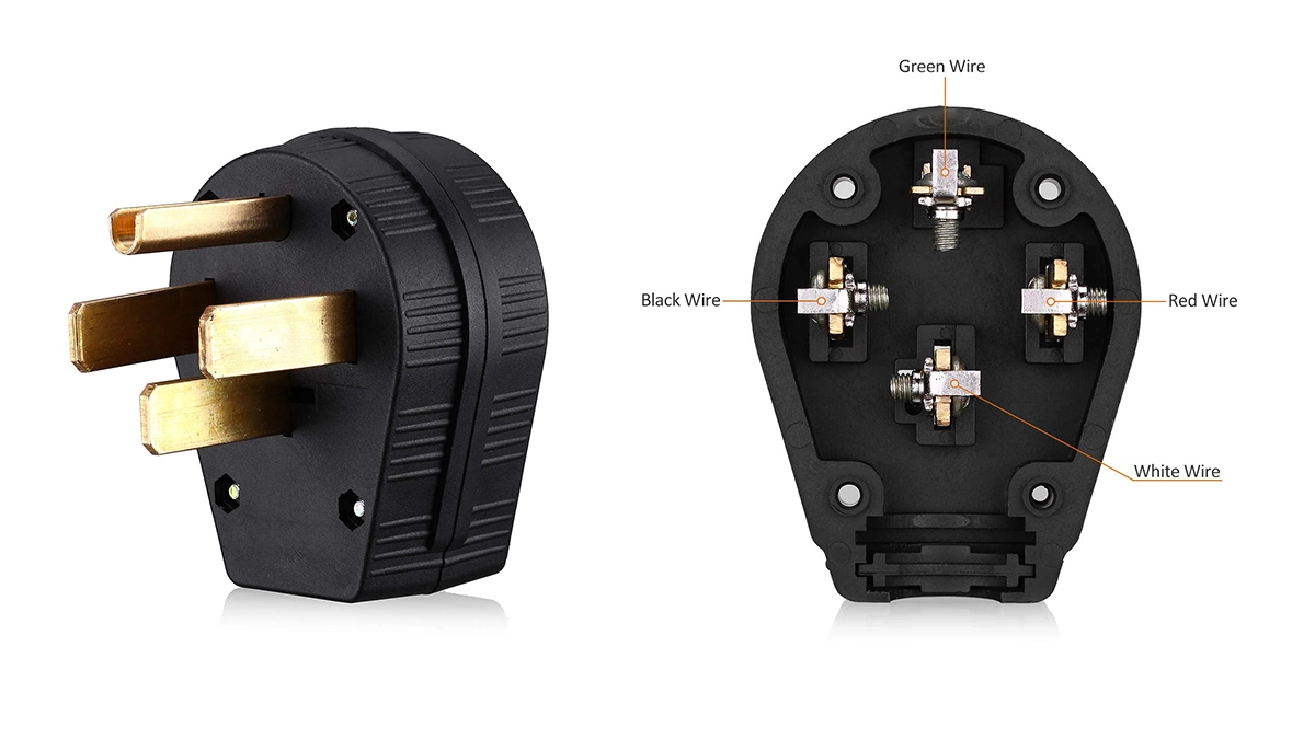
Plug-in Level 2 uses a dedicated outlet like NEMA 14-50 or 6-50. It is easier to replace or take with you. It also tends to have a slightly lower install cost because it resembles a heavy-duty appliance circuit. The safety hinge is the outlet and wiring quality. A properly installed outlet with the right wire gauge and a solid terminations stays cool under continuous load. A cheap or worn outlet can overheat over time.
Hardwired Level 2 is directly connected by an electrician. It has fewer failure points, no plug blades to loosen, and usually handles outdoor installs better. It is also the cleaner choice if you expect to upgrade current later. If you start with a plug-in 32A system and later want 48A, you might need a new outlet, new wire, or a different circuit. Hardwired setups avoid that rework most of the time.
A simple household view helps. If you want maximum long-term reliability and do not plan to move the charger, hardwired is often the best choice. If you rent, expect to relocate, or want a flexible backup solution, plug-in makes sense, as long as the outlet is installed to spec.
Two EVs at home: three setups that keep charging simple
When two EVs share one home, the right structure matters more than raw amperage. There are three common ways to do this well.
Shared-power single charger. One charger can detect two vehicles and split current. Either both cars charge at once at reduced power, or the system prioritizes one and then the other. Overnight, this feels hands-off. You plug both in and wake up with both ready.
Two linked wallboxes. Each car has its own charger, but the chargers talk to each other and cap the total current. This is tidy for side-by-side parking. It avoids overload while still giving both cars a place to plug in.
True dual-output units. One device with two cables and internal power allocation. It is the simplest physical setup for two cars in one spot, and the logic is handled inside the unit.
If both cars drive similar daily miles, shared-power is usually enough. If one car is a workhorse and the other is light-use, prioritization features can keep the main car topped up first. The key is letting the system manage power automatically so you never micromanage charging late at night.
Future-proofing your home setup: connectors and real-weather comfort
Connector standards are in transition. Many cars on the road today use J1772 for Level 2. Newer models increasingly use the NACS shape. For a home buyer, the goal is not to predict winners. The goal is to keep regret low. You can do that in a few ways. Choose a charger that can swap cable heads later. Use a clean adapter strategy for the car you do not own yet. Or select a setup that supports both standards without drama. Any of these paths keeps your home ready for the next vehicle without forcing a full replacement.
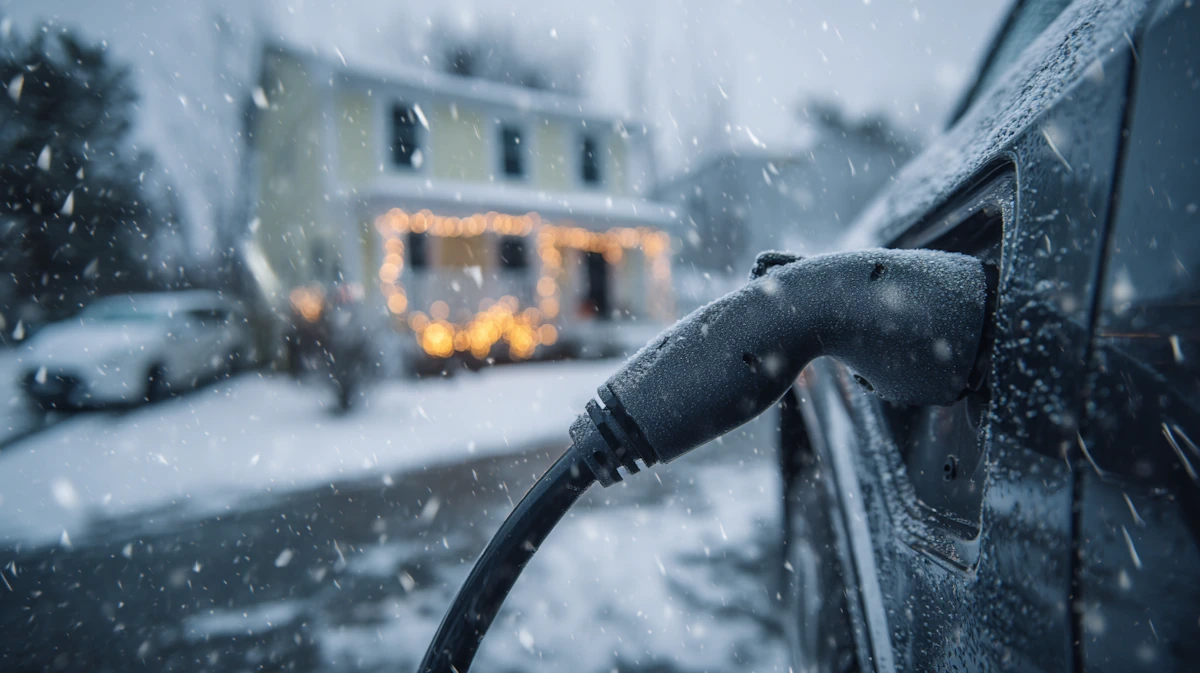
Now the part that decides whether you enjoy charging every day: real-weather usability. If your charger lives outdoors, or you deal with winter, cable quality becomes a daily experience issue. In cold climates, stiff cables are frustrating and can stress connectors. In coastal or humid areas, sealing and material aging matter more than headline amperage. If snow or freezing rain is common, you want a handle that stays easy to mate and release and a cable that does not turn into a rigid rod at night.
This is where a flexible backup option helps too. A Portable EV Charger can be a smart choice for rentals, travel, or multi-location use, and it also gives you a second path if your main wallbox is occupied by another car. For day-to-day comfort, pay attention to cable build and handle ergonomics. A good EV cable & connector makes home charging feel simple in bad weather, not like a workout.
A simple checklist before you buy
Run through this list once. If all of it feels right, your setup will feel right.
1. The charger has recognized safety certification and is rated for your install location.
2. Your panel has enough spare capacity, or you plan to use load management or scheduling.
3. You know whether a second EV is likely within two years, and your setup can share power if needed.
4. You have a low-regret connector plan for the next car, not just the current one.
5. Your circuit rating matches your continuous charging current.
6. You have decided plug-in versus hardwired based on reliability needs and how long you will stay in this home.
7. The outlet, wire gauge, conduit, and terminations (if plug-in) are spec-correct and built for continuous load.
8. Cable length fits your parking layout without strain or sharp bends.
9. Outdoor exposure, cold stiffness, and handle comfort have been considered, not treated as afterthoughts.
10. Smart features matter only if they save you money or simplify your routine, not because an app exists.
FAQ
Do I need a NEMA 14-50 outlet for Level 2 charging at home?
Not necessarily. A plug-in Level 2 setup often uses a NEMA 14-50 or 6-50 outlet, but many of the most reliable installs are hardwired and do not use a plug at all. The right answer depends on whether you want portability and easy replacement (plug-in) or maximum long-term reliability and fewer connection points (hardwired). Either way, the circuit must be dedicated and built for continuous load.
Is hardwired actually safer than plug-in?
Hardwired usually has fewer failure points because there is no plug and no outlet contact to loosen over time. Plug-in can still be safe when the outlet is industrial-grade, installed to spec, and the terminations are solid. The weak link is almost never the charger itself. It is usually the outlet quality, wire size, and how well everything was tightened and protected.
Can a 100A panel handle Level 2 charging?
Sometimes yes, sometimes no. A 100A service can be tight if you also run electric HVAC, dryers, ovens, hot tubs, or other large loads. The two practical paths are dynamic load management (the charger automatically reduces current when the home load rises) or time-sharing (charging runs when the home load is low, usually overnight). If you are unsure, a load calculation by a qualified electrician is the right way to avoid nuisance trips and overheating.
Should I pick a 32A, 40A, or 48A home charger?
Choose based on your “overnight window” and how many miles you need to replace on a normal day. For many homes, 40A continuous is the sweet spot because it refills comfortably overnight without pushing the panel hard. 48A makes sense when you drive long daily distances, have a short overnight window, or you know your electrical capacity is generous. 32A often feels identical to higher amps for lighter daily driving. Also remember the continuous-load rule: a 50A circuit supports 40A continuous charging, and a 60A circuit supports 48A continuous charging.
What is the cleanest setup for EV charging two cars at home?
Power sharing is usually the simplest and safest approach. A shared-power single charger, two linked wallboxes, or a true dual-output unit can split current or prioritize one car automatically. The goal is to avoid “brute amps” and instead let the system manage power in the background so both cars are ready by morning without manual switching.
Read More

 NEMA 14-50 for Portable EV Charging: What to Check First
 Portable EV Charger Power Plug Guide: NEMA vs IEC 60309 vs Wall Sockets
 What Is an On-Board Charger and an Off-Board Charger in an EV?
 AC vs DC EV charging: how it changes connector and cable design
 What Level of EV Charging Do Fleets Really Need?
 Level 1 vs Level 2 Home Charging: Which One Fits Your Life Better?
 EV Charging Levels Explained: Level 1, Level 2 and DC Fast Charging
 EV Charging Glossary (A–Z)
 Mode 1, 2, 3 and 4 EV Charging Explained: What Each One Is Used For
 Are Portable EV Chargers Worth It? A Practical Guide For Everyday Use
 Can You Really Charge an EV in 10 Minutes or Less?


 English


 IPv6 network supported
