 Safety Standards for EV Connectors in Different Regions
Sep 26, 2025
Safety is more than a plug that fits. For EV connectors, it blends three layers: electrical safety, functional safety, and connected-system security. Standards define how to build and test. Regulations decide what can be sold or installed. Procurement needs both in view, or uptime becomes guesswork.
Regional quick reference
Region
Common connectors
Core safety standards (examples)
Regulatory / conformity themes
Notes for buyers
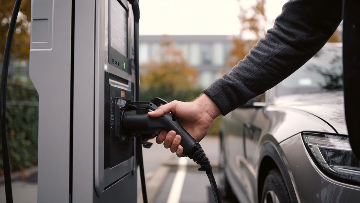
North America (US/CA)
J1772 (AC), CCS1 (DC), J3400
UL 2251 for connectors/couplers; UL 2594 for AC EVSE; UL 2202 for DC; UL 9741 for V2X; install per NEC 625
Funding rules and utility interconnect; accessibility and uptime language in tenders
Ask for NRTL listings, temperature-rise data, HVIL tests, cable strain evidence, and label photos
European Union / UK
Type 2 (AC), CCS2 (DC)
EN/IEC 62196 for connectors; EN/IEC 61851 for EVSE; EMC/LVD as applicable
AFIR for public networks; security obligations for connected gear; payment and price transparency
Look for a Declaration of Conformity with harmonized EN standards and security documentation for connected features
China (Mainland)
GB/T AC/DC; ChaoJi pathway emerging
GB/T 20234.x interfaces; GB/T 27930 communication
Domestic certification schemes and grid rules
Check edition years on GB/T certificates; verify comms conformance and pin temperature-rise results
Japan
CHAdeMO (DC), Type 1 (AC in legacy)
JEVS/CHAdeMO documents for DC; national electrical and EMC frameworks
Collaboration with ChaoJi pilots; local approvals for public sites
Confirm CHAdeMO certification and CAN messaging conformance
India
CCS2 (new public DC), legacy Bharat AC/DC
IS 17017 series based on IEC 61851/62196
BIS certification; DISCOM interconnect terms
Ask for BIS marks, enclosure IP evidence, ambient derating policy, and spare-parts plan
What the tests actually cover• Insulation, creepage, and clearance to limit arcing• Temperature rise on pins, terminals, and cable conductors at stated currents• Ground continuity and protective bonding• Mechanical integrity: drop, impact, latch durability, mating cycles• Environmental protection: IP rating, corrosion, UV aging, salt fog• Functional interlocks (HVIL), latch detection, safe de-energization before unmating• Material safety: flammability, tracking resistance, thermal indexes• For connected equipment: secure updates, credential policies, incident handling, and anti-fraud controls where payments exist
North AmericaPublic DC sites support CCS1 and, in many places, J3400 alongside it. Safety relies on the UL family. Inspect listing scopes for the exact connector and EVSE variants. Request temperature-rise curves at the currents and ambients you expect, not just a single point. Installation follows NEC 625 and local code. In tenders, uptime and payment access show up; pick connectors that expose readable sensors and have wear parts you can swap fast.
European Union and UKType 2 rules AC; CCS2 is standard for DC. EN/IEC 62196 and 61851 frame connector and EVSE safety. Treat security as part of safety if the product is connected: evidence for secure updates, credential rules, and user guidance matters. AFIR raises the bar on interoperability and payment clarity. Confirm the Declaration of Conformity cites the right harmonized standards and edition years. Make sure device identifiers and logs are accessible for audits.
ChinaGB/T 20234 defines the physical interfaces; GB/T 27930 aligns communication. Check that certificates match current editions and the purchased variant. Cable length and cross-section influence temperature rise, so match the tested configuration. If ChaoJi is on the roadmap, validate the mechanical, thermal, and handling path early, including cooling approach and cable mass.
JapanCHAdeMO remains central in many deployments. Verify certification currency, CAN messaging behavior, and cycle life. Where projects touch ChaoJi pilots, agree on adapter or migration steps and how site labeling will guide drivers during transition.
IndiaRollouts favor CCS2 for public DC; Bharat formats remain in legacy fleets. IS 17017 maps closely to IEC, but BIS marks and local utility approvals are required. Hot ambient and dust justify a closer look at derating and IP performance. In dense areas, confirm reach and strain relief around tight parking.
Recent changes (2024–2025)• North America: J3400 (standardized NACS) grows alongside CCS1; UL family remains the safety anchor; installation references NEC 625.• European Union/UK: beyond EN/IEC 62196 and 61851, connected products face security obligations under radio/cyber provisions; AFIR strengthens interoperability and payment clarity for public networks.• China: GB/T 20234 and GB/T 27930 editions have been updated; align certificates with current versions and with the purchased cable set; ChaoJi programs continue to advance.• India: IS 17017 aligns to IEC for new deployments; BIS certification and local utility approvals remain mandatory; CCS2 dominates new public DC.• Japan: CHAdeMO certification and CAN behavior remain central; collaboration paths with ChaoJi exist in pilots.
What counts as proof of conformity
• Certificates or listings that name the purchased variant, with edition years and model codes.• Summaries of critical tests: pin and terminal temperature-rise across ambient bands, dielectric strength, HVIL behavior, enclosure IP.• Label proofs: rating plate artwork or photos with serials/traceability and required warnings.• For connected equipment: a security note describing update and rollback processes, credential policy, and audit-log availability.
Safety standards get products admitted to the market; regional regulations decide how they are deployed; real-world performance still depends on matching the certified product to the site conditions. Keep the regional map in view, verify the edition years on certificates, and read the temperature-rise and HVIL data alongside your ambient and duty cycle.
FAQ
What’s the difference between standards and regulations for EV connectors?A: Standards (for example, IEC 62196/61851, UL 2251/2594) define how connectors and EVSE are designed and tested—dimensions, insulation, temperature-rise, interlocks, EMC. Regulations and codes (for example, AFIR in the EU, national radio/cyber provisions for connected gear, NEC 625 for installation in the US) decide what can be marketed, installed, and how it must behave in public networks. Certification/listing shows a product was tested to a specific edition of a standard; regulatory conformity shows it is legally deployable in that region.
Which connector families are used by region?A: North America uses J1772 for AC, CCS1 for DC, with J3400 growing alongside. The EU/UK use Type 2 for AC and CCS2 for DC. China uses GB/T (with a path toward ChaoJi in some programs). Japan uses CHAdeMO for DC and Type 1 in legacy AC contexts. India’s new public DC largely adopts CCS2, while some fleets still operate Bharat AC/DC formats.
What test results matter most on a datasheet or report?A: Prioritize temperature-rise at the pins/terminals across your ambient band (ask for the curve, not a single point), dielectric withstand, HVIL behavior and safe de-energization, enclosure IP rating, and mechanical cycle life of the latch/trigger. For connected equipment, ask how firmware is signed and updated, whether rollback is supported, and how audit logs can be exported. Label clarity (ratings, warnings, serials) is part of safety evidence—keep photos on file.
How can I verify conformity beyond seeing a certificate?A: Match model codes and options on the certificate to the exact variant you will buy (including cable length/cross-section). Check the edition years of the cited standards. Request label artwork or photos and a short summary of critical tests (temperature-rise, HVIL, IP). Run a brief on-site trial with several heavy sessions at target current and record temperatures and any derates. For connected units, request a security note that explains update and credential policies and confirms log export for audits.
Read More

 Do NACS to CCS adapters slow fast charging?
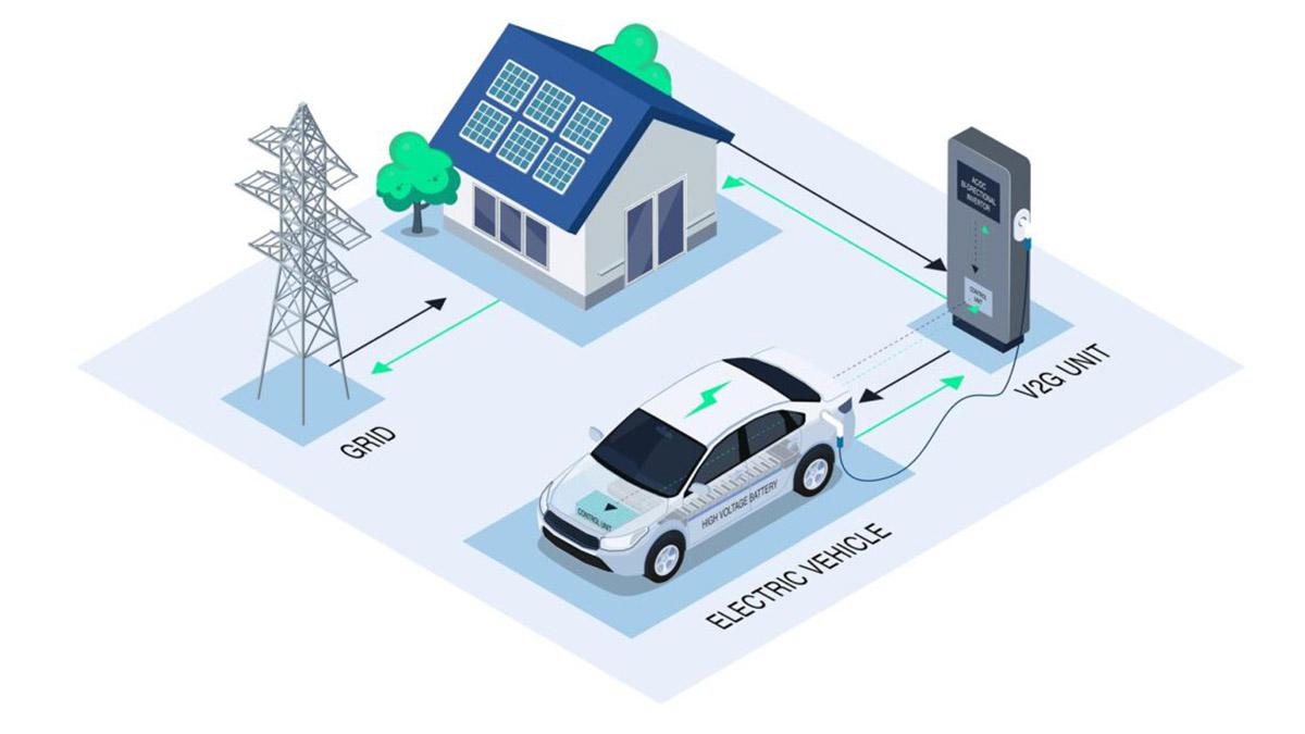 V2X Basics: How EVs Can Power Homes, Buildings and the Grid
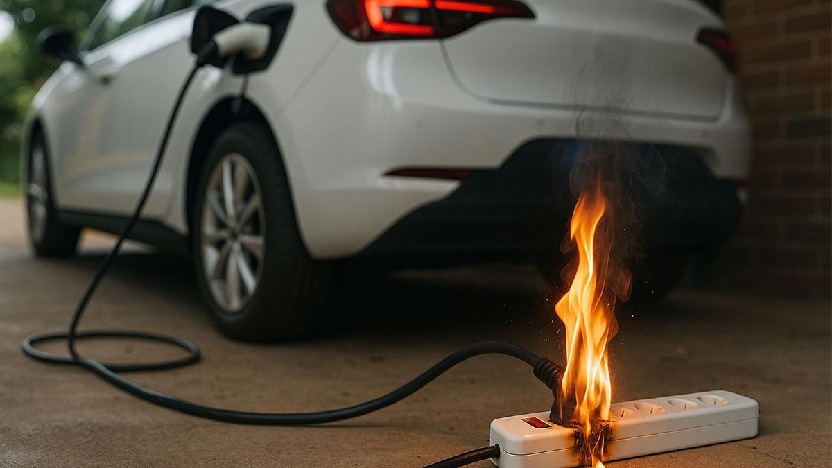 Why Mode 2 Charging Burns Power Strips and What to Do Instead
 How Many Amps Does a Home EV Charger Need? (Europe)
 Why High-Power CCS2 Sites Move to Liquid-Cooled Connectors
 EV Connector Selection for Public and Private Sites 2025
 Should I Charge My EV to 100%?
 How to Upgrade Existing Chargers to Support New Connectors
 Why EV Charging Slows After 80%
 The Role of ISO 15118 in EV Connector Communication (2025)
 How to Improve EV Charging Speed (2025 Guide)


 English


 IPv6 network supported
