How Contact Force and Geometry Affect EV Charging Connector Performance
Oct 26, 2026
A contact may perform well in an initial electrical check but behave differently after repeated mating. When that happens, contact force is one factor to examine alongside spring geometry, fit, material, and surface condition.
Contact force helps keep mating surfaces electrically connected. The spring’s geometry determines how it deflects and where pressure is applied. Together, these design features affect electrical performance, mating effort, and wear.
Three Forces, Three Different Measurements
Normal contact force presses the mating conductive surfaces together. Insertion and withdrawal force is the force needed to mate or separate the complete connector. Terminal retention force measures how securely a terminal is held in the housing.
The measurements are related, but they are not interchangeable. Insertion force includes resistance from the contacts and other parts of the assembly, such as seals and locking features. A high insertion force alone cannot tell you how much force is acting at an electrical contact. Terminal retention is a separate measurement, though terminal movement or misalignment can affect the mating interface.
How Geometry Shapes Contact Force
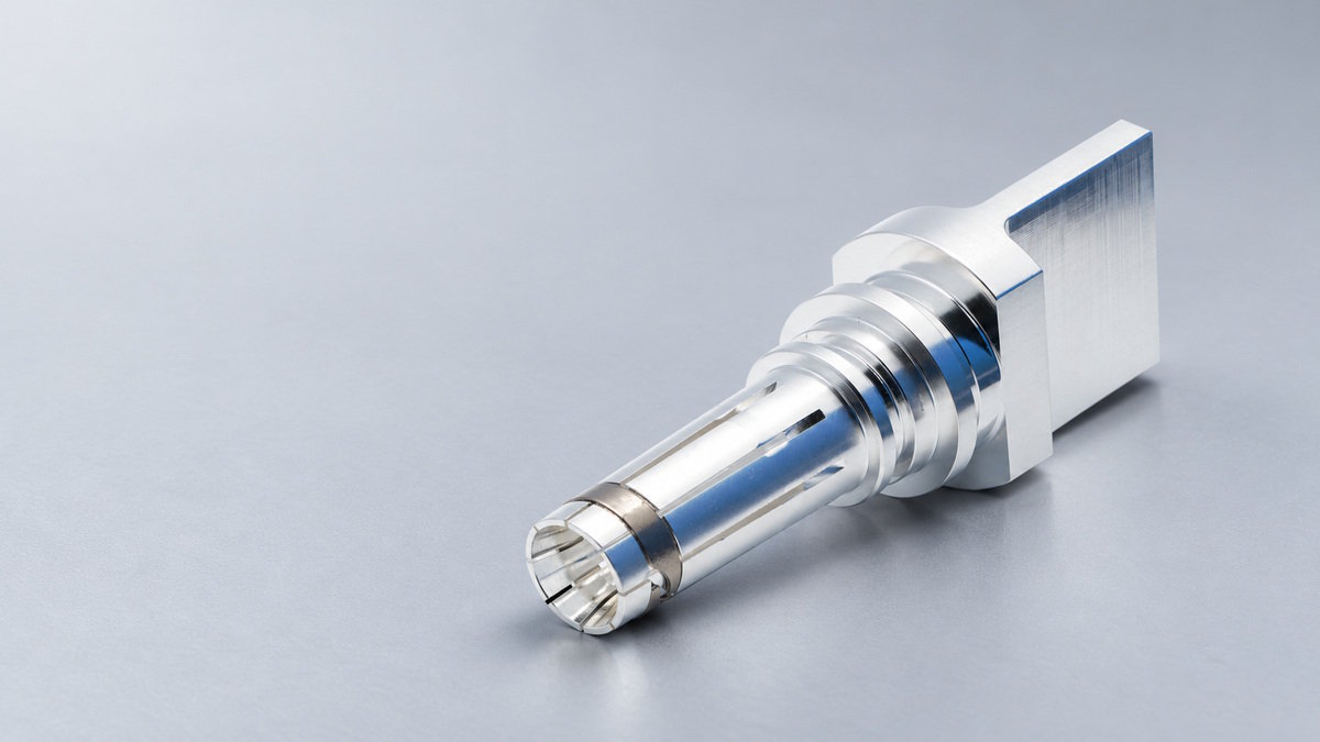
In a spring-contact design, the spring deflects as the mating pin enters. Beam length and thickness, curvature, slots, and the contact point all influence that deflection and the resulting force. The fit between the pin and socket matters too: dimensional variation can change how far the spring deflects in the assembled connector.
Geometry also affects how pressure is distributed and how the surfaces move against each other. Some designs use sliding contact, which can disrupt certain surface films under particular conditions. That movement also contributes to wear.
A geometry change can therefore affect several outcomes at once. Changing a beam’s dimensions may alter spring force; changing the contact point may alter pressure distribution or the sliding path. The result needs to be measured in the complete contact design.
How Does Contact Force Affect Resistance and Wear?
Metal surfaces meet at microscopic high points rather than across their full apparent area. Contact force can deform these points and create conductive paths. That can reduce constriction at the interface, but the result also depends on materials, plating, surface condition, and dimensional fit.
More force does not automatically mean lower resistance or longer life. If the surface is damaged or the parts do not fit correctly, increasing force may not address the cause. It may also increase resistance to sliding during mating and affect wear. The impact on insertion force depends on the full connector assembly.
When considering a change, compare the electrical result with the mechanical result. An improvement in one does not establish that the overall design is better.
Evaluating a Geometry Change
Consider a design review focused on resistance that changes after repeated mating. The team can compare the initial and post-cycle measurements, then inspect the contact surfaces and spring condition for wear, deformation, or changes in fit.
If the evidence points to the contact geometry, the team can compare a revised spring design with the baseline. Before testing, define what the change is expected to do—for example, alter spring deflection or contact position. Then measure contact resistance and insertion or withdrawal force under repeatable conditions. Temperature rise can also be useful under current, but it reflects the complete current path and heat dissipation, so it should be interpreted alongside the electrical and mechanical measurements.
Repeat the relevant checks after the required mating cycles. If resistance improves but insertion force or wear exceeds the project’s limits, the change has shifted the trade-off. If resistance still changes after cycling, inspect the surfaces and fit before assuming that more force is needed.
This is an illustrative design evaluation, not a report of a specific product or test result. Acceptance limits and test conditions depend on the connector and its application.
A geometry change is useful when the measurements show that it addresses the original performance issue and does not create a larger problem elsewhere in the connector.
FAQs
Can insertion force be used to estimate contact force?
No. Insertion force measures the force needed to mate the complete connector. It includes resistance from the electrical contacts and other parts of the assembly, such as seals and locking features. It can indicate how much force is needed to mate the connector, but it does not show the force acting at an individual electrical contact. Contact force, insertion and withdrawal force, and terminal retention force are separate measurements.
Does higher contact force always reduce contact resistance?
No. Contact force can help create conductive paths between microscopic high points on the mating surfaces, but resistance also depends on material, plating, surface condition, and dimensional fit. Increasing force may not address a damaged surface or poor fit. It may also increase resistance to sliding during mating and affect wear. Electrical and mechanical results should be assessed together.
What should be checked when contact resistance changes after repeated mating?
Compare contact resistance measurements taken before and after the required mating cycles under repeatable conditions. Inspect the contact surfaces and spring for wear or deformation, and check the fit between the pin and socket. These checks can help investigate possible links to contact geometry, surface condition, or fit before a design change is considered.
How should a spring-contact geometry change be evaluated?
First define what the change is expected to do, such as altering spring deflection or contact position. Compare the revised design with the baseline under repeatable conditions, measuring contact resistance and insertion or withdrawal force. Repeat the relevant checks after the required mating cycles and inspect for wear. Temperature rise can also be measured while current flows, but it reflects the complete current path and heat dissipation, so it should be interpreted alongside the electrical and mechanical measurements. Test conditions and acceptance limits depend on the connector and its application.
Read More








 English