 Smart EV Charging Explained: A Simple Guide
Oct 27, 2025
What smart EV charging isSmart EV charging is software-assisted charging that: 1) shifts charging to cheaper hours, 2) keeps circuits within safe limits, and 3) reduces stress on the grid. It’s the same cable and power, but timing and current adapt to price, capacity, and need.
How it worksThere are three flows working together.Power flow: grid or onsite solar → meter/panel → charger → vehicle battery.Control signals: your app or a schedule sets the charge rate and start/stop rules.Billing data: session start/stop, kWh and tariff details go to your app or a back office.If the network drops, a solid setup keeps a local fallback: a safe default current, the last saved schedule, and manual start/stop on the charger.
Core featuresTime-of-use (TOU) scheduling. Start at off-peak hours and finish before the morning spike.Dynamic load balancing. Share limited capacity across two EVs or several charge points without tripping breakers.Circuit caps. Hold the charger below a fixed amp limit that matches your wiring and breaker.Remote monitoring and updates. See progress, get alerts, and install firmware without a site visit.PV and storage integration. Match charging to rooftop output or a battery’s cheap-energy window.Demand response basics. Allow small, short power trims during grid events in exchange for a credit.
What changes when you turn on smart featuresBefore / After: Home with TOU pricingScenario: North America, off-peak 23:00–06:00, price 0.18 → 0.10 $/kWh. Goal: add 30 kWh overnight.Before: plug and charge at 18¢ → about $5.40.After: schedule for 23:00 at 10¢ → about $3.00.Result: roughly 44% lower cost with no extra steps.
Two EVs sharing one circuitScenario: circuit limit 40 A; Car A needs 20 kWh; Car B needs 10 kWh; window 21:00–07:00.Before: both pull 20 A; other appliances push the circuit toward nuisance trips.After: dynamic sharing. Car A takes priority at 32–35 A until ~01:30; Car B then gets 20–25 A; total stays ≤40 A.Result: no trips, both cars ready by morning, no midnight car shuffling.
Workplace or public site with a site capScenario: site cap 180 kW; six cars arrive at once in the evening.Before: early arrivals hog power; late arrivals crawl; demand charges spike.After: start each car ~30 kW, adjust by remaining time or priority; during peak, trim to 20–25 kW; restore off-peak.Result: smoother waits and a predictable bill without breaching the cap.
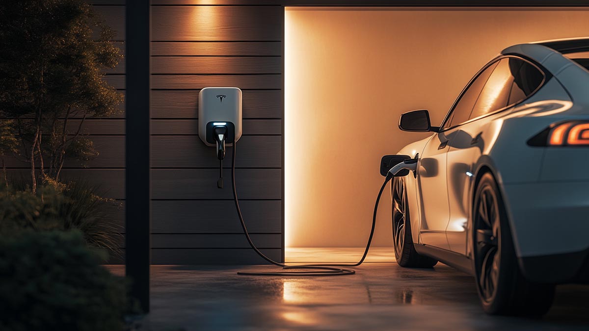
Home setup: make it work with your panelYour car’s onboard charger sets the ceiling for AC speed. A 7.4 kW wallbox will not exceed a car limited to 7.2 kW. Keep wiring runs short and correctly sized to limit voltage drop and heat.
Two practical presetsNorth America, single EV overnight: schedule 23:00–06:00 and cap current at 32–40 A on a 50–60 A circuit. This usually restores 25–35 kWh overnight at off-peak rates and leaves headroom for other loads.
Europe, two EVs on one supply: with 3-phase 11 kW, enable load sharing; give Car A priority to 80% by 02:00, then hand power to Car B at 8–10 A until 06:00.An adjustable-current portable EV charger helps match different household circuits and keeps sessions steady; Workersbee portable EV charger fits this use case without adding steps for the user.
Public sites and workplacesPower is shared, so allocation rules matter. Build trust through the first seconds of a session: the connector seats with a click, authentication works the first time (RFID, app, or Plug & Charge), current holds steady, and the receipt arrives automatically.
Keep alerts focused: temperature rises, residual-current trips, and breaker events should trigger a remote check or soft reset before sending a technician. Choose payment flows that are fast for repeat users and simple for first-timers.
Fleets and depotsPlan with rules, not one-off sessions. Inputs are departure windows, minimum SOC targets, a site power cap, and any demand-charge guardrails. A minimal rule set works well: priority vehicles reach 80% by 05:30, non-priority fill to 60–70%, and the site never exceeds its cap. During expensive windows, trim per-vehicle power in small steps rather than hard stops so vehicles still leave on time without creating price spikes.
Hardware, software, and standardsInteroperability. Aim for at least OCPP 1.6J; plan for 2.0.1 if you want richer energy management and future services.
Connectivity. Prefer Ethernet, then Wi-Fi, then LTE; two paths improve uptime.Metering. If you bill by kWh, pick chargers with calibrated meters and tamper seals.
ISO 15118 and Plug & Charge. Faster, cleaner starts when both the car and charger support it.
Longevity. Look for sturdy cables, durable connectors, good thermal behavior, and a vendor that ships timely firmware updates.
Workersbee products and services for smart chargingPortable charging for homes and small sites• Workersbee portable EV charger: adjustable current settings to match different household circuits; simple scheduling through a clear interface; robust enclosure for daily use; options for Type 1/J1772 or Type 2 applications.
• Benefits: safer starts on limited circuits, easy overnight schedules, and consistent session behavior even when the network is unavailable.
DC connector hardware for shared-power and high-current sites• Workersbee CCS2 liquid-cooled DC connector: designed for stable high current with effective thermal management during long sessions at public hubs and depots.
• Workersbee CCS2 Gen1.1 naturally-cooled DC connector: a durable option for 250–375 A sites where simplicity and weight also matter.
• Benefits: repeatable latch feel, manageable handle weight, and cable/connector durability that helps sites hold target currents in smart load-sharing setups.
Engineering support and integration• OEM/ODM support: connector and cable customization, labeling, and harness options to fit charger or site layouts.
• Compliance and testing: routine mechanical, electrical, and environmental tests to align with market requirements.
• Interoperability focus: guidance on pairing hardware with OCPP-based backends and site energy management so smart features (scheduling, load sharing, price rules) work as intended.
FAQ
Does smart charging work without internet?Yes. Keep a local schedule and manual start/stop available; your session will continue even during a brief network drop.
Will smart features slow charging?Only if you choose to cap current, avoid peak prices, or share power across multiple vehicles. The goal is predictable results, not unnecessary delays.
Can I use rooftop solar with these products?Yes. Schedule sessions for midday or let the system follow a solar-first window; adjustable current helps you match output and circuit limits.
Which connector should a public site choose?If your bays frequently run long high-current sessions, a liquid-cooled CCS2 connector helps manage heat and keep currents steady. For moderate current ranges and simpler maintenance, a naturally-cooled CCS2 option is practical.
How do I start with a two-EV household?Set a night window, enable load sharing, and give the first car priority until a target SOC (for example 80% by 01:30), then let the second car take the remainder of the window.
Tell us your use case—home, workplace, or depot—and the limits you’re working with (circuit size, site cap, target vehicles). We’ll return a concise configuration checklist and suggest matching hardware options such as Workersbee portable EV charger for home setups and Workersbee CCS2 DC connector choices for shared-power public sites.
Read More

 The Role of ISO 15118 in EV Connector Communication (2025)
 NACS vs CCS (CCS1 & CCS2) in 2025: Power, Access, Adapters, Reliability


 English


 IPv6 network supported