Home

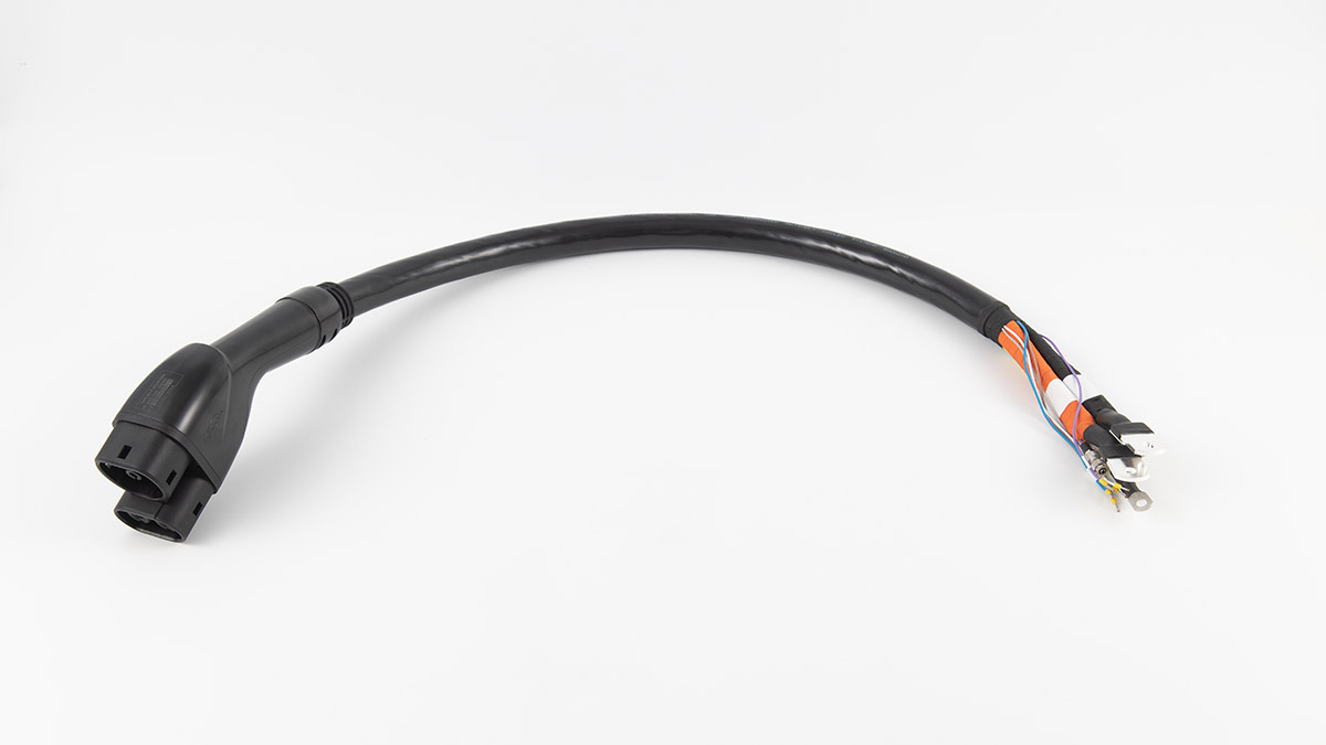
liquid-cooled CCS2 connector

  • Liquid-Cooled EV Charging: Water vs Oil Choices Liquid-Cooled EV Charging: Water vs Oil Choices
    Oct 15, 2025
    Why liquid cooling is on the tableHigh current creates heat in conductors and at contact interfaces. If that heat isn’t carried away, temperatures rise, contact resistance worsens, and cables become heavy and stiff when you try to solve it with more copper. A closed liquid loop moves heat from the connector/cable to a radiator so power stays high and handling stays friendly.     Two routes in one view Water-based (water–glycol)High specific heat capacity and higher thermal conductivity. Excellent at bulk heat transport. Because water-glycol conducts electricity, it stays behind an insulated boundary; heat crosses through an interface into the coolant. Flow behavior in cold weather is generally predictable with the right mixture and materials.   Degradable synthetic oilIntrinsically insulating, so some designs can bring it closer to hotspots. Specific heat and thermal conductivity are lower than water-glycol, so the system compensates via surface area, flow control, or duty-cycle management. Many oils thicken more at low temperatures; design for start-up and winter service.     What’s inside the loopCirculation unit with pump, radiator/fan, and reservoir → flexible lines routed through the cable and handle → sensors for liquid level, temperature, and pressure → station software that watches trends and raises alarms. Different cable lengths change flow resistance; longer runs need more pump head and careful routing.      Property snapshot Property Water–Glycol (typical) Synthetic Cooling Oil (typical) What it means on site Specific heat (kJ/kg·K) ~3.6–4.2 ~1.8–2.2 Water-based moves more heat per kg per degree rise Thermal conductivity (W/m·K) ~0.5–0.6 ~0.13–0.2 Faster heat pickup on the water side for the same area Electrical behavior Conductive → needs insulated interface Insulating Oil can be closer to energized parts (still needs sound sealing) Low-temperature viscosity Moderate rise Often steeper rise Oil systems need more attention to cold-start flow Materials compatibility Metals, elastomers must suit glycol Metals, elastomers must suit oil Choose seals/hoses per coolant family     How to choose: a simple path     Start from load, not headlinesDefine the current range you’ll see most of the day (not the marketing peak), the typical session length, and whether sessions arrive back-to-back. This shapes the heat you must remove each minute, and the “recovery time” between sessions.   Map the climate and enclosureDeep-cold regions push you to consider start-up viscosity, line routing, and warm-up behavior. Hot, dusty, or salty air demands unobstructed airflow and filter discipline at the radiator.   Decide how close the coolant can goIf you want the coolant very near hotspots, insulating oils simplify the electrical side; if you prefer a robust insulated boundary and maximum heat transport per liter, water-glycol is compelling.   Check pump head and line lossesCable and hose length, bends, and quick-connects all add resistance. Ensure the pump can maintain target flow under that resistance. As a rule of thumb for high-current cables, designs commonly target several bar of available pump head; many systems for fast-charging cables operate around the high single-digit bar range to stay comfortable with longer paths and small-diameter passages.   Size the radiator by recovery, not only by peakYou’re designing for repeatability: stable temperatures across consecutive sessions. Pick cooling capacity so the system returns to a steady baseline fast enough for your site’s traffic pattern.     Scenario → focus → engineering move Scenario What to watch Practical move Deep cold Start-up flow and bubbles Favor stable low-temp viscosity; design a smooth vent/fill; verify trend back to baseline Back-to-back sessions Heat accumulation and recovery Strengthen heat path and radiator margin; monitor time-to-baseline Dusty/salty air Radiator airflow, seals Keep intake/exhaust clear; routine filter cleaning; seal inspection Long cable runs Flow resistance, handling Gentle routing, stress relief, sensible bend radius; ensure pump head margin Tight cabinets Hot-air recirculation Duct hot air out; avoid recirculation into the intake     Working example A site runs many sessions at a high current level. Resistive losses in cables and contact interfaces turn into heat Q that must be removed by the loop. The loop removes heat by raising coolant temperature across the cable segment and dumping it at the radiator.   If your average heat to remove is on the order of hundreds of watts to a few kilowatts (typical for high-power leads under sustained load), then at a 5–10 °C coolant rise you’re moving on the order of 0.02–0.2 kg/s of water-glycol. For oil, expect higher mass flow (or higher ΔT, or more area) to move the same heat because of lower specific heat and conductivity.   Longer hoses and tighter passages require more pump head to keep that flow. Plan pump head with margin so flow doesn’t collapse when filters load or lines age.     Monitoring that actually prevents downtime Trend temperature, don’t just chase a threshold. A slow rise at the same load says the loop is getting “dirty” (minor seepage, air, filter loading, fan wear).   Watch level and pressure together. Stable level but falling pressure suggests restrictions; falling level with noisy pressure hints at air ingestion or seepage.   Instrument health matters. A tired fan or pump still “runs,” but the thermal curve will tell you it’s fading.   Alarm closure must be visible. It’s not an alarm until someone received it and acted.   Compliance as three lines of defenseMaterials and geometry that keep coolant and conductors in their lanes → real-time sensing with redundancy for temperature/level/pressure → station alarms that reach responsible teams with a clear handoff to resolution.   Commissioning and routine careFill and vent the loop properly; confirm that temperature, level, and pressure read correctly in the station software; walk the hoses for rub points; keep contacts clean; log quick checks. Small routines prevent big problems.   Water vs oil Choose water-glycol when bulk heat transport and predictable cold-weather flow are top priorities, and an insulated heat-exchange boundary fits your design philosophy.   Choose synthetic oil when electrical insulation at the coolant is strategically useful, you can design for cold-start viscosity, and you want closer proximity to hotspots without an extra insulated wall.     Key takeawaysDesign for the current you actually deliver, the climate you live in, and the cadence of your traffic. Pick the coolant family that matches those realities, give the pump and radiator honest margins, and monitor trends. Do this well and fast charging stays quick, stable, and easy to handle—session after session.
    Read More
  • Why High-Power CCS2 Sites Move to Liquid-Cooled Connectors Why High-Power CCS2 Sites Move to Liquid-Cooled Connectors
    Sep 22, 2025
    High current changes everything. Once a CCS2 site aims beyond the mid-300-amp range for long stretches, heat, cable weight, and driver ergonomics become the real constraints. Liquid-cooled connectors move heat out of the contact and cable core so the handle stays usable and power stays up. This guide explains when the switch makes sense, what to look for in the hardware, and how to run it with low downtime.     What really breaks at high current– I²R loss drives temperature at contacts and along the conductor.– Thicker copper reduces resistance but makes the cable heavy and stiff.– Ambient heat and back-to-back sessions stack; afternoon queues push shells past limits.– When the connector overheats, the controller derates; sessions stretch and bays back up.     Where natural cooling still winsNaturally cooled handles work well for moderate power and cooler climates. They avoid pumps and coolant. Service is simpler and spares are cheaper. The trade-off is sustained current in hot seasons or under heavy duty.     How liquid cooling solves the problemA liquid-cooled CCS2 connector routes coolant close to the contact set and through the cable core. Heat leaves the copper, not the driver’s hand. Typical assemblies add temperature sensing on power pins and in the cable, plus flow/pressure monitoring and leak detection tied to safe shutdown.     Decision matrix: when to move to liquid-cooled CCS2 Target current (continuous) Typical use case Cable handling & ergonomics Thermal margin across the day Cooling choice ≤250 A Urban fast chargers, low dwell Light, easy High in most climates Natural 250–350 A Mixed traffic, moderate turnover Manageable but thicker Medium; watch hot seasons Natural or Liquid (depends on climate/duty) 350–450 A Highway hubs, long dwell, hot summers Heavy if natural; fatigue rises Low without cooling; early derating Liquid-cooled ≥500 A Flagship bays, fleet lanes, peak events Needs slim, flexible cable Requires active heat removal Liquid-cooled     Workersbee CCS2 liquid-cooled at a glance– Current classes: 300 A / 400 A / 500 A continuous, up to 1000 V DC.– Temperature rise target: < 50 K at the terminal under stated test conditions.– Cooling loop: typical 1.5–3.0 L/min flow at about 3.5–8 bar; around 2.5 L coolant for a 5 m cable.– Heat extraction reference: about 170 W @300 A, 255 W @400 A, 374 W @500 A (published data supports engineering of higher-amp scenarios).– Environmental: IP55 sealing; operating range −30 °C to +50 °C; acoustic output at the handle under 60 dB.– Mechanics: mating force under 100 N; mechanism tested for more than 10,000 cycles.– Materials: silver-plated copper terminals; durable thermoplastic housings and TPU cable.– Compliance: designed for CCS2 EVSE systems and IEC 62196-3 requirements; TÜV/CE.– Warranty: 24 months; OEM/ODM options and common cable lengths available.     Why drivers and operators feel the difference– Slimmer outer diameter and lower bend resistance improve reach to ports on SUVs, vans, and trucks.– Cooler shell temperatures reduce re-plugs and failed starts.– Extra thermal headroom keeps set power flatter during afternoon peaks.   Reliability and service, kept simpleLiquid cooling adds pumps, seals, and sensors, but design choices keep downtime low. Workersbee focuses on field-swappable wear parts (seals, trigger modules, protective boots), accessible temperature and coolant sensors, clear leak-before-break paths, and documented torque steps. Techs can work quickly without pulling the whole harness. A two-year warranty and >10k mating-cycle design align with public-site duty.     Commissioning notes for high-power bays Commission the hottest bay first. Map contact and cable-core sensors; calibrate offsets. Stage holds at 200 A, 300 A, and target current; record ΔT from ambient to handle shell. Set current-versus-coolant curves and boost windows in the controller; enable graceful taper. Monitor three numbers: contact temperature, cable inlet temperature, and flow. Alert policy: “yellow” for drift (rising ΔT at the same current), “red” for no-flow, leak, or over-temp. On-site kit: pre-filled coolant pack, O-rings, trigger module, sensor pair, torque sheet. Weekly review: plot power hold time vs ambient; rotate bays if one lane heats earliest.     Buyer scorecard for CCS2 liquid-cooled connectors Attribute Why it matters What good looks like Continuous current rating Drives session time Holds target amps for an hour in hot weather Boost behavior Peaks need control and recovery Stated boost time plus auto-recovery window Cable diameter & mass Ergonomics and reach Slim, flexible, true one-hand plug-in Temperature sensing Protects contacts and plastics Sensors on pins and in cable core Coolant monitoring Safety and uptime Flow + pressure + leak detect + interlocks Serviceability Mean time to repair Swap seals, triggers, and sensors in minutes Environmental sealing Weather and washdowns IP55 class with tested drain paths Documentation Field speed and repeatability Illustrated torque steps and spares list     Thermal reality checkTwo conditions stress even good hardware: high ambient temperature and high duty cycle. Without liquid cooling, the controller must derate earlier to protect contacts. Using a liquid-cooled CCS2 handle lets the site sustain target current for longer, trimming queues and stabilizing per-bay revenue.   Human factorsDrivers judge a site by how quickly they can plug in and walk away. A stiff cable or hot shell slows them down and raises error rates. Slim, liquid-cooled cables make ports easier to reach and allow a natural, comfortable plug-in angle.   Compatibility and standardsThe CCS2 signaling stays the same; what changes is the heat path and the monitoring. Build acceptance around temperature rise, shell temperature, and fault handling. Keep per-bay records of current, ambient, contact temperature, and taper points to support audits and seasonal tuning.   Cost of ownership, not just CapExFrequent derating costs more in longer sessions and walk-offs than it saves on hardware. Factor session time at your top ambient bins, tech time for common swaps, consumables (coolant, filters if used), and unplanned downtime hours per quarter. For high-duty hubs, liquid-cooled connectors win on throughput and predictability.     Where Workersbee fits Workersbee’s liquid-cooled CCS2 handle is built for steady high current and easy upkeep, with field-accessible sensors, quick-swap seals, a quiet grip, and clear torque steps for technicians. Integration notes cover flow (1.5–3.0 L/min), pressure (about 3.5–8 bar), power draw under 160 W for the cooling loop, and typical coolant volume per cable length. This helps sites bring flagship bays online quickly and hold power in hot seasons without moving to bulky cables.     FAQ At what current should I consider liquid cooling?When your plan calls for sustained current in the upper-300-amp range or higher, or when your climate and duty cycle push shell temperatures up. Is liquid cooling hard to maintain?It adds parts, but good designs make the usual swaps quick. Keep a small kit on site and log thresholds. Will drivers notice the difference?Yes. Slimmer cables and cooler handles make plug-ins faster and reduce mis-starts. Can I mix bays?Yes. Many sites run a few liquid-cooled lanes for heavy traffic and keep naturally cooled lanes for moderate demand.
    Read More
  • How to Improve EV Charging Speed (2025 Guide) How to Improve EV Charging Speed (2025 Guide)
    Sep 10, 2025
    Glossary • SoC: battery state of charge, shown as a percentage.• Charge curve: how power rises, peaks, then tapers as SoC increases.• Preconditioning: the car warms or cools the battery before a fast charge so it’s at the right temperature.• Peak power: the maximum kW your car can draw, usually only for a short burst.• Power sharing: a site splits power between stalls when many cars plug in.• BMS: the car’s battery management system that keeps the pack safe and sets charging limits.     Why is the same car fast today and slow tomorrowThree scenes explain most slow sessions. 1. Cold morning. You may arrive with the cabin toasty but the battery still cold, and the car will reduce charging power to protect the cells.   2. Hot afternoon. Cable and electronics run hot. The system reduces power to hold safe temperature.   3. Busy site. Two or more stalls pull from the same cabinet. Each car gets a slice, so your power drops.     The charge curve explained Fast at low SoC, slower near full. Most cars charge quickest below roughly 50–60 percent, then taper as they pass 70–80 percent. The last 10–20 percent is the slowest part. If you need to save time, plan for short stops in the fast zone instead of one long session to near 100 percent.       What drivers can control in minutes• Navigate to the fast charger in your car’s system before you set off. This triggers battery preconditioning on many models.• Arrive low, leave smart. Reach the site around 10–30 percent, charge to the range you need, often 70–80 percent, then go.• Pick the right stall. If cabinets are labeled A–B or 1–2, choose a stall that is not paired or not in use.• Check the handle and cable. Avoid damaged connectors, tight kinks, or hot-to-the-touch cables.• Avoid back-to-back heat. If your car or the cable feels hot after a long drive, a five-minute cool-off with the car in Park can help the next ramp.     What site owners can control• Available power. Size cabinets and grid feed for peak times, not only averages.• Power allocation. Use dynamic sharing so a single active stall gets the full output.• Thermal design. Keep inlets, filters, and cable routing clear; add shade or airflow in hot climates.• Firmware and logs. Keep charger and CSMS software up to date; watch for stalls that derate early.• Maintenance. Inspect pins, seals, strain relief, and contact resistance; swap worn parts before they cause drop-offs.     Quick diagnostic path when charge is slower than expectedStep 1 — Check the car:• SoC above 80 percent → taper is normal; stop early if time matters.• Battery too cold or too hot warning → start preconditioning, move the car into shade or out of wind, retry. Step 2 — Check the stall:• Paired stall light is active or neighbor is charging → move to an unpaired or idle stall.• Cable or handle feels very hot, or visible damage → switch to another stall and report it. Step 3 — Check the site:• Many cars waiting, site at capacity → accept a reduced rate or route to the next hub on your path.     Action plan scorecard Situation Quick move Why it helps Typical result Arrive with high SoC Stop sooner; plan two short stops Stays in the fast zone of the curve More kWh per minute overall Cold battery in winter Precondition via car navigation Brings cells into the optimal window Higher initial kW Hot cable or stall Change to a shaded or idle stall Lowers thermal stress on hardware Less thermal derate Paired stalls are busy Pick an unpaired cabinet output Avoids power sharing More stable power Unknown slow-down cause Unplug, replug after 60 seconds Resets session and handshake Recover lost ramp     Cold and hot weather tipsWinter: Start preconditioning 15–30 minutes before arrival. Park out of strong wind while waiting. If you do short hops between chargers, the pack may never warm up; plan one longer drive before your fast stop.Summer: Shade matters. Canopies reduce heat on chargers and cables. If you tow or climb hills before charging, give the car a short cool-off with HVAC on but drive unit at rest.     How connectors and cables affect your speed windowThe charger cabinet sets the ceiling, and your car sets the rules, but the connector and cable decide how long you can stay near peak power. Lower contact resistance, clear heat paths, and good strain relief help the system hold current without early derating. In high-traffic sites, liquid-cooled DC cables widen the usable high-power window, while naturally cooled assemblies work well at moderate currents with simpler upkeep. Workersbee focus: Workersbee liquid-cooled CCS2 connector uses a tightly managed thermal path and accessible sensor layout to help sites hold higher current longer, with field-serviceable seals and defined torque steps for quick swaps.     Operations playbook for site owners• Design for the dwell you promise. If you market 10–80 percent in under 25–30 minutes for typical cars, size your cabinets and cooling for warm days and shared use. • Map cabinet-to-stall pairing in your signage. Drivers should know which stalls share a module. • Add human factors. Cable length, reach angles, and parking geometry change how easily drivers plug and route the cable. Shorter, slimmer cables reduce mishandling and damage. • Build a five-minute inspection. Look for pitted pins, loose latches, torn boots, and hot spots on thermal cameras during peak hours. Log any stall that tapers too early. • Keep spares ready. Stock handles, seals, and strain relief kits so a tech can restore full speed in one visit.     Common myths, clarifiedMyth: A 350 kW charger is always faster than a 150 kW unit.Reality: It depends on your car’s max accept rate and where you are on the charge curve. Many cars never draw 350 kW except for a short spike.   Myth: If power drops after 80 percent, the charger is faulty.Reality: Taper near full is normal and protects the battery. Stop early if you are in a hurry.   Myth: Cold weather always means slow charging.Reality: Cold plus no preconditioning is slow. With preconditioning and a longer drive before your stop, many cars can still charge briskly.     Driver checklist•  Set the fast charger as your destination in the car’s navigation so preconditioning starts automatically.• Arrive low, leave around 70–80 percent if time is key.• Choose an idle, non-paired stall.• Avoid damaged or overheated cables.• If speed is poor, unplug and retry on another stall.     Light maintenance cues for attendants• Clean and check the connector’s pins and seals every day.• Keep cables off the ground and avoid tight bends along the run.• Note stalls that show early derate or frequent retries; schedule a deeper check.• Review logs weekly for temperature alarms and handshake errors.     What this means for fleets and high-use sitesFleets live on predictable turn-times. Standardize driver behavior, keep the fastest stalls clearly signed, and protect thermal performance with shade and airflow. If you operate mixed hardware, tag which stalls hold current longest during summer peaks and route queuing there first. Workersbee can help by matching connector and cable sets to your cabinet ratings and climate. Workersbee naturally cooled and liquid-cooled assemblies are built for repeatable handling and quick field service, which supports consistent dwell times during busy hours.     Key takeaways• Charging speed follows a curve, not a single fixed number. Use the fast zone and avoid the slow tail.• Temperature and sharing are the two biggest hidden factors.• Small habits make big differences: precondition, arrive low, pick the right stall.• For sites, thermal design and upkeep keep high current alive longer.
    Read More

Need Help? leave a message

Leave A Message
Submit

home

products

whatsApp

contact