 Can You Turn On or Use an Electric Car While Charging?
Nov 06, 2025
Yes, you can usually turn on an electric car while it is charging, but only for cabin functions. You can sit inside, use the screen, run the air conditioning or heater, and adjust settings. You cannot shift into Drive or Reverse, and you cannot drive away until charging stops and the connector is removed.
What You Can and Cannot Do While an EV Is Charging
Question
Usually allowed?
Short answer
Can you turn on an EV while charging?
Yes
Cabin systems can usually operate.
Can you sit inside the car while charging?
Yes
It is normally safe if the charging session is normal.
Can you use AC or heater?
Yes
It may slightly reduce net charging speed.
Can you shift into Drive or Reverse?
No
The vehicle should block movement while plugged in.
Can you drive away while charging?
No
Stop charging and remove the connector first.
Can You Turn On an Electric Car While Charging?
Usually, yes. In most EVs, turning the car on during charging means the cabin and basic electronic systems can operate. The display may stay active, the climate system may run, and the driver may still be able to adjust settings.
That does not mean the vehicle is ready to move. A car can appear active while charging, but the charging connection and safety controls still prevent normal driving.
This is where many search questions overlap. Can you turn the car on? Usually yes. Can you drive it while plugged in? No. The vehicle is designed to separate comfort functions from movement functions during charging.
Can You Start an EV While It Is Plugged In?
This question often refers to the same situation, but the wording can be confusing. In many models, pressing the start button powers the vehicle systems, not the drive function.
So if starting means turning on the screen, climate control, or cabin electronics, that is usually possible. If starting means shifting into drive and leaving, it is not. The charging system is built to prevent that.
This matters in both home and public charging. Once the connector is engaged, the vehicle should remain stationary until the session ends and the cable is removed.
Is It Safe to Sit in an EV While Charging?
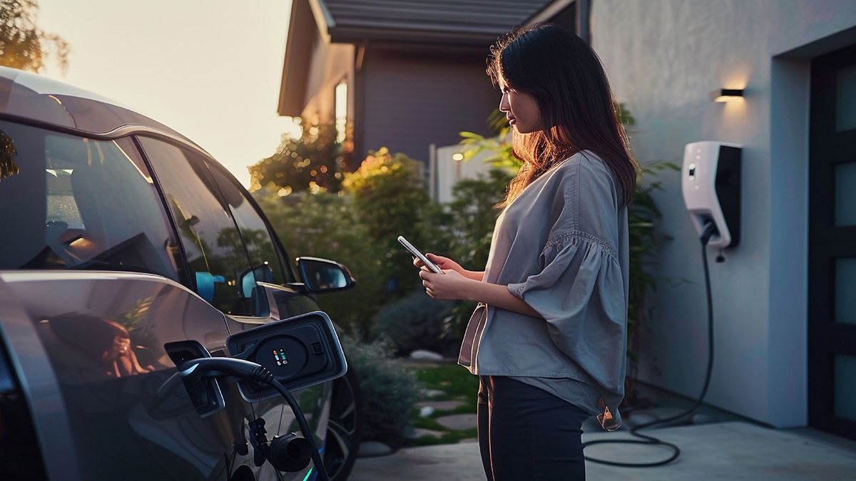
Under normal charging conditions, it is generally safe to sit inside an EV while it is charging. Many drivers do this during both home charging and public charging stops, especially when the weather is hot or cold.
The more important question is whether the charging session itself is normal. The connector should fit correctly, the cable should look intact, and the vehicle or charger should not show warnings. Sitting in the vehicle is usually not the issue. Damaged equipment, poor contact, or overheating is where the real concern begins.
If anything feels unusual, the session should be stopped and checked. Visible cable wear, a loose connector, error messages, or excessive heat should never be ignored.
Can You Use AC, Heater, Lights, and Infotainment While Charging?
In most cases, yes. Climate control, infotainment, cabin lighting, and similar low-power functions are usually available while charging.
What changes is how the incoming power is used. Some of that energy goes to battery charging, while some may support cabin comfort and electronics. Because of that, the net charging result can be slightly lower when these systems are running.
The effect is often more noticeable during lower-power AC charging. During higher-power charging, the impact may feel smaller, but it still exists. That is why some drivers notice slower battery gain when heating or cooling is working during a session.
This does not mean those functions should be avoided. It simply means charging and cabin use are sharing energy at the same time.
Why You Cannot Drive an EV While It Is Plugged In
An EV cannot be driven away while charging because the charging system and vehicle controls are designed to block movement during an active connection.
The reason is simple. If a vehicle could move while the cable was still connected, it could damage the connector, the inlet, the charger, or the surrounding area. Preventing movement protects both equipment and users.
This is why a vehicle may look active while still being locked out of normal driving. The cabin can work, but the vehicle is not in a drivable state until charging ends and the connector is removed.
For drivers, the easiest rule to remember is this: active does not mean drivable.
Does Using the Car While Charging Affect Charging Speed?
It can. If the air conditioning, heater, lights, or infotainment system is running, part of the incoming energy is being used outside the battery pack.
How noticeable that feels depends on charging power and cabin load. A light cabin load may have very little effect. Strong heating or cooling, especially during slower charging, can have a more visible impact.
This is one reason some drivers feel that charging is slower than expected when they stay in the car with climate control running. The session is still working, but not all incoming energy is going into stored battery charge.
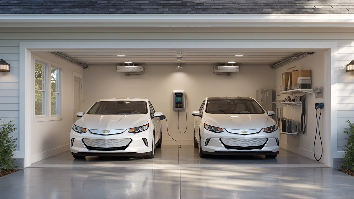
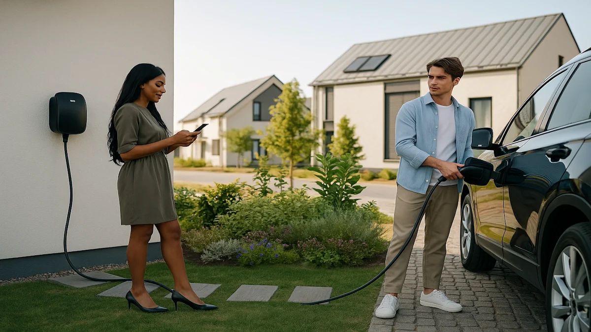
Home Charging vs. Public Charging
The basic rule stays the same in both cases: some onboard functions can be used, but the vehicle cannot be driven while plugged in.
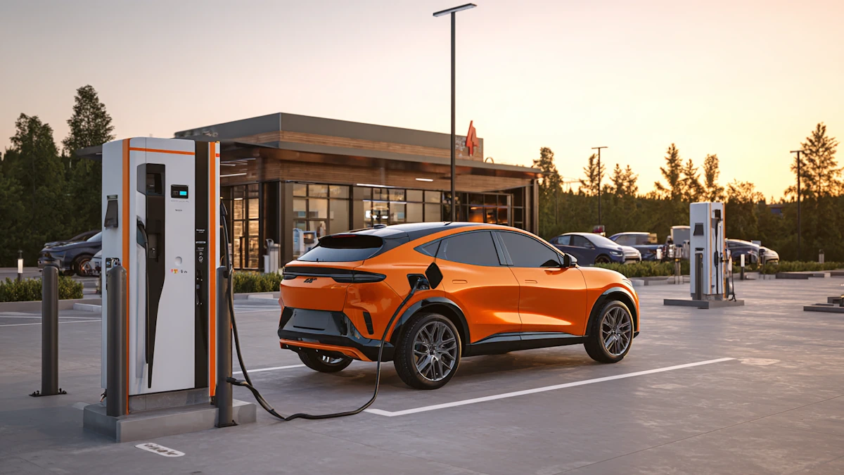
At home, charging is often slower and lasts longer, so cabin use can be easier to notice in the final charging result. At a public fast charging site, the incoming power is much higher, so the same cabin load may feel less important.
The user experience is also different. At home, drivers often leave the vehicle and let it charge overnight. In public, they are more likely to stay inside, use the screen, adjust navigation, or run heating and cooling while waiting.
Best Practices While Charging
Use charging equipment that matches the vehicle and application. A stable connection is the first step to a safe session.
Check the connector, cable, and inlet before charging. If anything looks worn, damaged, loose, or unusually hot, it should not be ignored.
Use cabin functions when needed, but remember they may slightly reduce net charging performance.
Do not try to override vehicle safety controls. If the vehicle will not enter a drive state while plugged in, that is working exactly as intended.
For charging businesses and equipment buyers, this is also where product quality matters. Well-designed charging components, including reliable EV charging connectors and cables, help support stable sessions and reduce avoidable issues in daily use.
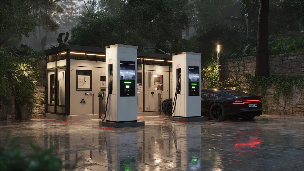
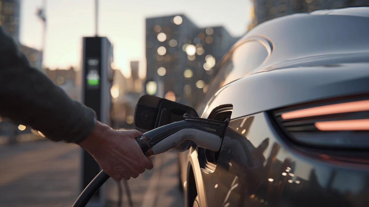
Charging Safety Also Depends on the Connector and Cable
A normal charging session also depends on the condition of the EV Connector, EV Cable, and vehicle inlet. A loose connector, worn cable, damaged insulation, or abnormal heat around the charging port can create safety risks. Before using cabin systems while charging, make sure the connector fits firmly, the cable is not damaged, and the charging session starts normally.
For home and destination charging, a reliable portable EV charger and a well-matched charging cable help keep the charging process stable. For public and fleet charging, connector durability, cable quality, and thermal performance are especially important because the equipment is used more frequently.
FAQ
Can I turn on my EV while charging?
Yes. In most EVs, you can turn on cabin systems while the car is charging. You can use the screen, lights, climate control, and other low-voltage functions. However, the vehicle should not allow you to shift into Drive or Reverse while the charging connector is plugged in.
Can I start an electric car while it is plugged in?
Usually yes, but “start” means powering on cabin functions, not driving the vehicle. An EV can normally wake up while charging, but it should stay immobilized until charging stops and the connector is removed.
Is it safe to sit in an electric car while charging?
Yes, it is normally safe to sit inside an electric car while it is charging, as long as the charger, connector, cable, and vehicle inlet are in good condition. If you notice abnormal heat, warning messages, smoke, burning smells, or a loose connector, stop charging and move away from the vehicle.
Can I use air conditioning or heat while charging?
Yes. You can usually use air conditioning or heating while charging. This may slightly reduce the net charging speed because part of the incoming power is used by the climate system instead of going directly into the battery.
Can an electric car drive while charging?
No. An electric car should not be able to drive while the charging connector is plugged in. The vehicle and charging system are designed to prevent movement during charging for safety reasons.
Does using cabin systems slow down EV charging?
Yes, but usually only slightly. Screens, lights, air conditioning, and heating consume some power. The effect is more noticeable on slower AC charging than on high-power DC fast charging.
Conclusion
An electric car can usually power cabin systems while charging, so drivers can often stay inside, remain comfortable, and use basic functions during a charging session. The boundary is clear: using the vehicle is not the same as driving it. Once the connector is engaged, the car is designed to remain in a safe, stationary state.
For users, that makes charging more practical. For charging providers and equipment buyers, it is also a reminder that safe, stable charging depends on both vehicle design and dependable hardware.
Read More

 Can You Really Charge an EV in 10 Minutes or Less?
 Two EVs at Home: One Charger or Two?
 How to Use Public EV Chargers
 How to Tell If Your EV Is Actually Charging
 How EV Charging Stations Actually Work
 Are EV Chargers Universal in 2026? A Practical Compatibility Check from Workersbee
 Fast or Slow? Navigating the Levels of EV Charging
 Are All Level 2 EV Chargers the Same?
 What Is EVSE? A Complete Guide to Electric Vehicle Supply Equipment and How It Works
 What Is EV Range? A Simple Guide for Everyday Drivers
 The Practical Guide to Type 2 EV Charging Cables


 English


 IPv6 network supported