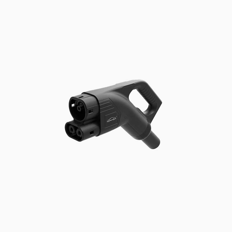
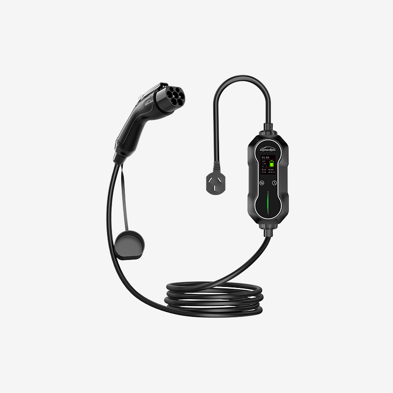
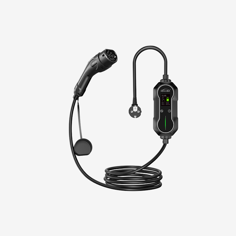
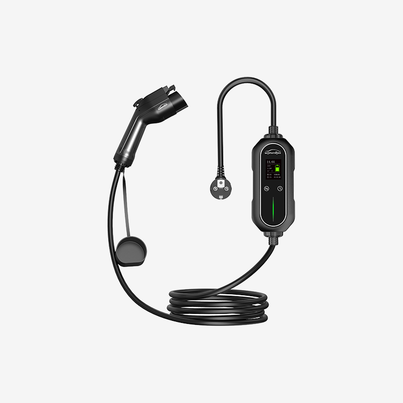
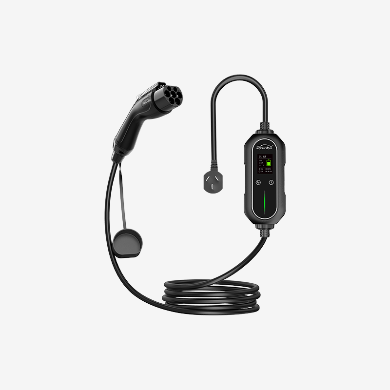
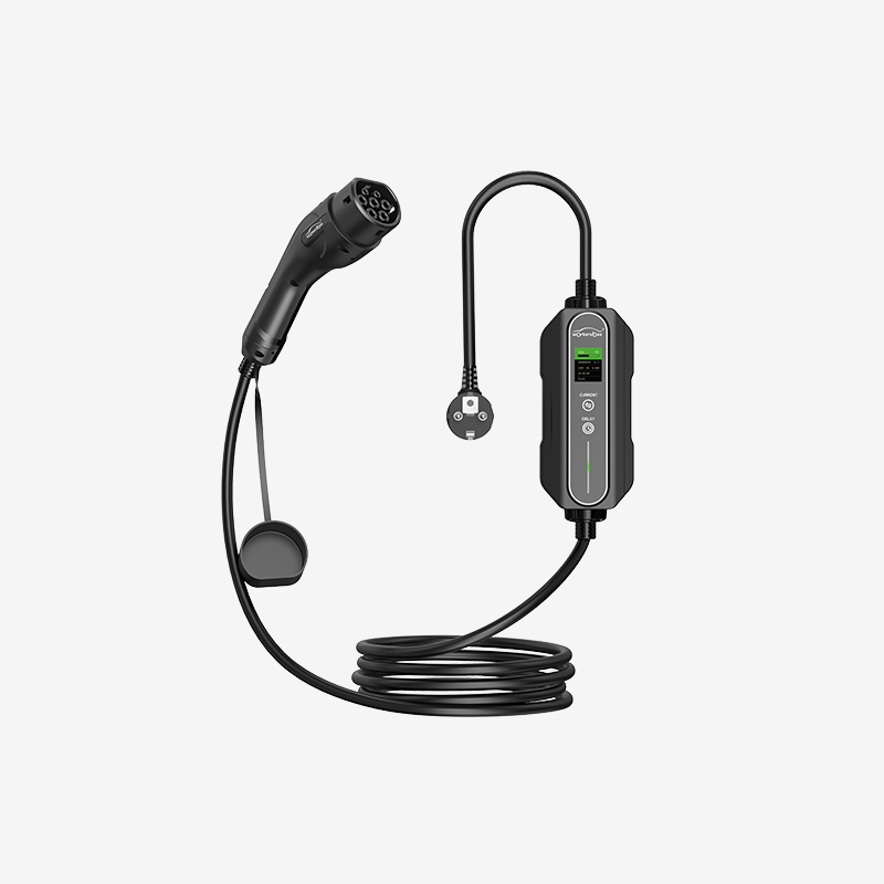
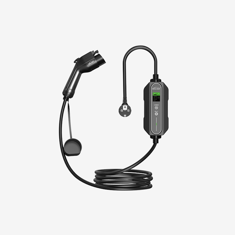
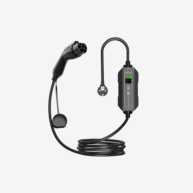
Home

electric truck fast charging

  • Megawatt Charging System (MCS) Guide for Heavy-Duty EVs: Power, Cooling, and Site Planning Megawatt Charging System (MCS) Guide for Heavy-Duty EVs: Power, Cooling, and Site Planning
    Sep 01, 2025
    Megawatt Charging System (MCS) is an emerging DC fast-charging approach for heavy-duty electric vehicles with high daily energy demand. It targets a high-voltage, high-current operating window and uses liquid-cooled hardware to manage heat at megawatt duty cycles. This lets a single stop deliver meaningful energy without turning routes into charging schedules. The goal is simple: turn a regulated rest break or a depot turnaround into real “refueling” time for trucks and coaches.   This page is a practical hub for MCS decisions. It covers session math, connector and cable cooling, fleet-focused control and logging, interoperability assumptions, and site sizing logic. It also includes a rollout checklist to align vehicles, EVSE, connector assemblies, and operations before pilots scale.     On this page · What MCS is and what it is not · Why fleets care · How an MCS session works · Power and energy per stop · Cooling and temperature limits · Control, logging, and uptime · Standards and interoperability · Where MCS will show up first · MCS vs passenger-car DC fast charging · Pitfalls in early pilots · Sizing an MCS site · Storage and peak management · Serviceability, uptime, and safety · Procurement and rollout checklist · FAQ · Connector and cable hardware considerations     What MCS is and what it is not MCS is a high-power DC charging architecture designed for heavy-duty EVs such as long-haul trucks, tractors, intercity coaches, and other high-utilization commercial vehicles. Industry roadmaps often discuss a voltage window reaching roughly the 1 kV class (with some references up to about 1,250 V) and current capability in the multi-kiloamp range (figures around 3,000 A are commonly cited). Actual delivered power and sustained current depend on the vehicle charge curve, cable thermal design, ambient conditions, and the derating strategy used to keep contacts and accessible surfaces within safe limits.   MCS is not “a bigger car charger.” Passenger-car DC fast charging is often occasional and opportunistic. MCS is engineered for repeatable, high-energy sessions where downtime is expensive and schedules are tight. That duty cycle changes decisions around cables, cooling, wear parts, commissioning, and service workflow.     Why fleets care Heavy-duty operations already have charging windows. Drivers have mandated breaks, coaches have fixed dwell times, and depot fleets run predictable shift cycles. The challenge is energy: vehicles need enough kWh per stop to keep routes intact.   MCS targets those windows. If a stop can consistently deliver hundreds of kWh, fleets can reduce extra charging stops, avoid unnecessary battery oversizing, and keep schedules stable. Charging becomes part of the operating plan, not an exception.     How an MCS session works A stable MCS session is more than “plug in and push power.” The sequence below is useful for commissioning and for diagnosing field failures. It also clarifies which events should be logged on both the vehicle and EVSE side. 1. Vehicle arrives and is positioned at the bay. 2. Coupler mates with the vehicle inlet. 3. Safety and insulation checks complete. 4. Authorization and authentication succeed. 5. Vehicle and EVSE negotiate voltage and current limits. 6. Thermal supervision is enabled (contacts, cable, and key hotspots). 7. Power ramps up to the negotiated limit. 8. Steady-state delivery continues with dynamic derating as needed. 9. Power ramps down in a controlled way; metering and logs are finalized. 10. Unlatch/unmate; session record syncs to backend systems.   For early projects, define a minimum logging set from day one: negotiated voltage/current limits, ramp behavior, temperature snapshots, fault codes on both sides, and the session end cause. Without this, intermittent failures are hard to triage.     Power and energy per stop Two numbers matter at first pass: peak power and delivered energy per stop. Power is voltage multiplied by current. Energy is power multiplied by time, minus losses and battery acceptance limits.   A quick reality check: · A 1,000 kW session over 30 minutes is about 500 kWh gross from the charger (1 MW × 0.5 h = 0.5 MWh). · What reaches the battery depends on the vehicle’s charge curve and system losses. · Sustained power matters more than a brief peak for route planning.   A practical planning model uses three multipliers: session gross energy (charger output), end-to-end efficiency (charger + cable + vehicle), and usable window (how long the vehicle can stay near high power). Even rough estimates are valuable because they show scale and constraints.   Cooling and temperature limits At megawatt duty cycles, the cable assembly becomes a system, not a commodity. High current increases resistive heating and raises surface temperature risk for drivers. For hand-handled couplers at multi-kiloamp currents, liquid cooling is the practical mainstream approach to control temperature and cable mass, especially under repeated duty cycles.   A durable design usually combines the items below, and treats them as operational requirements rather than optional features: · Liquid-cooled conductors to limit temperature rise without making the cable unmanageable. · Temperature supervision near heat sources (contacts and high-current paths). · A graceful derating strategy that protects safety while keeping sessions useful.   Ergonomics is not cosmetic in MCS. Gloves, rain, dust, night work, and time pressure are normal. Handling affects both safety and throughput.   Control, logging, and uptime In commercial operations, control and data are part of the charging system. Reliability depends on predictable session start behavior, robust fault handling, and logs that let teams diagnose issues quickly.   Key capabilities to plan for: · Smooth session start (readiness checks and consistent start conditions). · Power negotiation across the operating window, including ramps and limits. · Metering and reporting aligned with fleet workflows. · Fault logging that can be correlated between vehicle and EVSE. · Remote diagnostics and secure update paths to reduce truck rolls.   These items directly affect availability metrics. When control is fragile, fleets see sessions that fail to start, stop mid-session, or behave inconsistently across vehicles. That becomes lost route capacity, not a minor inconvenience.   Standards and interoperability MCS is defined as an ecosystem rather than a single component. Teams get the most value by separating what is stable enough for pilots from what will evolve as more field data accumulates.   A procurement stance that reduces risk: · Specify interoperability test scope (vehicles, EVSE, operating conditions). · Define firmware update expectations and responsibility boundaries. · Require shared fault log formats so field issues can be triaged quickly.   Early deployments should assume commissioning retests and software tuning are normal. Plan for them explicitly in schedules and acceptance criteria.   Where MCS will show up first MCS adoption is strongest where energy demand per vehicle is high and downtime is costly. Early sites typically focus on: · Freight corridors where each stop must add substantial route recovery. · Intercity coach hubs with fast turnarounds and reserved stands. · Ports and logistics terminals with repeated daily cycles. · Mines and construction environments with long shifts and limited windows. · High-utilization depot operations that need predictable throughput.     MCS vs passenger-car DC fast charging A cabinet and a cable can look similar on the outside. Under the hood, the design constraints are different. The table below summarizes the practical differences that show up in deployments.   Aspect Passenger-car DC fast charging Megawatt Charging System (MCS) Typical vehicle Cars and light vans Trucks, tractors, buses, specialty heavy EVs Typical power ~50–350 kW ~750 kW to 1 MW+ (depends on system limits) Duty cycle Occasional, opportunistic Daily, high-energy, repeatable Stop pattern Driver-chosen, irregular Tied to schedules, breaks, depot flow Cable strategy Air-cooled or modest cooling Liquid-cooled high-current assemblies (mainstream) Handling Light cable, small handle Heavier system, ergonomics engineered Service model General station maintenance Wear-aware parts strategy, faster swaps Uptime impact Inconvenience Direct operational loss (routes, depots, commitments)   The consequence is that MCS sites should be treated like industrial assets. Cable management, spare parts, technician access, and fault workflow matter as much as nameplate power.   Pitfalls in early pilots These issues show up repeatedly in pilots and can derail timelines if they are not addressed early: 11. Chasing peak power instead of repeatable throughput. 12. Underestimating cable handling and serviceability. 13. Treating cooling as an accessory instead of an operational system. 14. Pushing interoperability testing too late in the project. 15. Missing shared fault logging across vehicle and EVSE. 16. Using site power assumptions that ignore simultaneity and ramp behavior. 17. No credible plan for growth beyond the first site.   Sizing an MCS site Site planning starts with honest assumptions: how many vehicles will charge concurrently, typical session length, arrival SOC distribution, and how power will be allocated across bays. The objective is to size for operational reality, then validate with measured data.   Example: a four-bay MCS site (illustrative only) Assume four dispensers each rated at 1 MW. If operations rarely hold all bays at peak simultaneously, a diversified peak can be lower than nameplate. A placeholder simultaneity factor (for example, 0.6 as an illustration) would imply ~2.4 MW diversified peak for a 4 MW nameplate site. Transformer sizing and grid interconnection must follow local utility requirements, detailed load studies, and the site’s demand-charge structure.   Topology choices that improve utilization · Shared DC architectures can route power across bays. · Power allocation logic can prioritize vehicles with earlier departures. · Modular cabinets can reduce rework as utilization grows.   Storage and peak management On-site storage can shave short overlaps, support brief disturbances, and help a smaller grid connection feed higher short-duration delivery. Even without storage, power management can coordinate ramps, reduce unnecessary peaks, and align charging priority with operational urgency.   Treat peak management as a design input. If it is bolted on later, peak costs and underutilization tend to become permanent.   Serviceability, uptime, and safety Megawatt sites often fail in small ways before they fail in big ways. Physical details decide whether uptime is steady or painful.   Design for field service from day one: · Protect cooling lines and cable paths from impact and vehicle traffic. · Ensure technician access to pumps, filters, and heat exchangers. · Match ingress protection to dust, moisture, and road-grime conditions. · Provide ventilation and, where needed, enclosure thermal management. · Plan drainage and cleaning in real depot conditions.   Safety behavior at high power typically depends on layered protection. Commissioning should test rushed coupling, poor weather, and partial failures, not only ideal lab conditions. · Isolation and lockout strategies. · Insulation/leakage monitoring. · Emergency-stop coverage across dispensers and cabinets. · Controlled management of abnormal conditions. · Temperature supervision and safe derating behavior. · Ergonomic placement so manual coupling remains practical under pressure.     Procurement and rollout checklist This checklist is designed to prevent pilot surprises by forcing alignment across vehicles, EVSE, connector assemblies, cooling, software, and operations.   Vehicle compatibility · Inlet location and access with trailer geometry and bay design. · Supported voltage window and maximum current today. · Communication profile and update strategy (vehicle firmware plan).   Power strategy · Dispenser rating today and target rating later. · Power allocation capability across bays. · Expandability without full civil rework.   Cooling and service · Cooling loop service intervals and field procedures. · Fill, purge, and leak-check responsibilities. · Field-replaceable modules and target swap time.   Software and operations · Authentication methods and fleet workflows. · Session reporting and log retention. · Secure update paths and remote diagnostics.   Commissioning and quality checks · Interoperability tests with target vehicles under controlled conditions. · Thermal validation under repeated duty cycles. · Baseline KPIs: utilization, success rate, efficiency, station availability.   A practical rollout method is to treat the first site as a pilot while designing it so the lessons scale to a corridor or regional network.     FAQ How fast is MCS in day-to-day use? Early demos often target meaningful energy delivery in about half an hour, but real results vary by charge curve, temperature, arrival SOC, and the station’s sustained power capability.   Will passenger cars use MCS? MCS is tailored to heavy-vehicle geometry, energy use, and duty cycles. Passenger vehicles are likely to remain on lighter connectors and power levels that match smaller packs and easier handling.   Is liquid cooling necessary? For megawatt-class current through a hand-handled connector, liquid cooling is the practical mainstream approach to keep cable size, weight, and temperature within safe handling limits, especially under repeated duty cycles.   What should buyers assume about interoperability? Expect commissioning retests and software tuning as deployments expand. Define test scope, update expectations, and shared fault logging up front so issues can be triaged quickly.     Connector and cable hardware considerations Connector and cable decisions show up everywhere: thermal limits, driver handling, service workflow, and station uptime. A partner with high-current DC experience can help translate megawatt goals into maintainable assemblies and realistic field behavior. Workersbee develops high-current connector and cable components that map to MCS requirements, especially around liquid-cooled operation and service-friendly cable assemblies through EV charging connectors and MCS connector solutions.   For early deployments, treat the connector and cable assembly as a lifecycle system, not just a line item. The best pilots are built to scale—technically, operationally, and financially.
    Read More

Need Help? leave a message

Leave A Message
Submit

home

products

whatsApp

contact