 What Is a Type 2 EV Connector? A Plain Guide to the 7-Pin AC Plug (2025)
Oct 20, 2025
Type 2 is the 7-pin AC charging interface widely used across Europe and many nearby regions for home, workplace, and destination charging. This guide explains the Type 2 connector pinout, including L1, L2, L3, N, PE, CP, and PP, plus basic wiring reference notes, AC charging power levels, and the difference between Type 2 and CCS2.
For buyers, operators, and technical teams, the key point is simple: Type 2 is for AC charging, while CCS2 is used for DC fast charging. A reliable Type 2 connection depends not only on the plug shape, but also on correct pin functions, CP/PP signaling, cable rating, and the vehicle’s onboard charger limit.
Type 2 Connector Pinout: What the 7 Pins Do
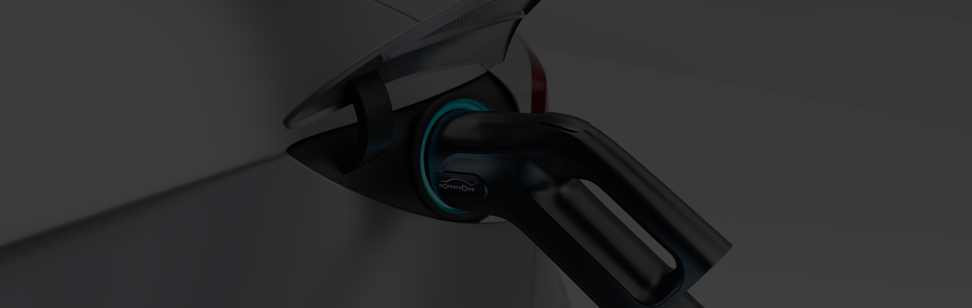
A Type 2 connector has seven contacts: L1, L2, L3, N, PE, CP, and PP. The power pins support single-phase or three-phase AC charging, while CP and PP help the vehicle and charging equipment confirm connection status, current limits, and safe charging behavior.
Pin
Function
What It Does
L1
AC live phase 1
Supports single-phase or three-phase AC charging
L2
AC live phase 2
Used for three-phase AC charging
L3
AC live phase 3
Used for three-phase AC charging
N
Neutral
Provides the neutral path for AC power
PE
Protective earth
Provides grounding protection
CP
Control pilot
Handles charging control, status signaling, and current limit communication
PP
Proximity pilot
Helps detect plug connection and cable current rating
This 7-pin layout is the reason Type 2 can support both simple home AC charging and higher-power three-phase AC charging. The connector is not just a power interface. It also includes control and safety signals that help the charging equipment and the vehicle communicate before and during charging.
Type 2 Plug Wiring Reference and Signal Flow
A Type 2 plug wiring reference is mainly used to understand how the seven contacts work together. L1, L2, L3, N, and PE handle the AC power path, while CP and PP handle control and detection signals.
In a typical AC charging process, the charging equipment first detects whether the connector is properly inserted. Then the vehicle and EVSE confirm available current through the control signal. Once the charging system confirms that the connection is safe, AC power can be supplied to the vehicle’s onboard charger.
This information is useful for connector selection, product comparison, technical communication, and specification review. It is not intended for unauthorized field wiring or cable assembly. Actual cable design, installation, repair, or modification should follow local electrical regulations and be handled by qualified professionals.
CP and PP Pins in a Type 2 Connector
CP means Control Pilot. It helps the vehicle and charging equipment manage charging status, available current, start/stop behavior, and basic safety communication. Without the CP signal, the charging equipment cannot correctly confirm whether charging should begin, continue, or stop.
PP means Proximity Pilot. It helps identify plug connection and cable current capacity. This allows the charging system to recognize the cable rating and avoid exceeding the safe operating limit of the cable assembly.
Together, CP and PP make the Type 2 connector more than a simple power plug. They are part of the safety and control logic behind AC EV charging.
Type 2 AC Charging Power: 7.4 kW, 11 kW, and 22 kW
The charging speed depends on three factors: site supply, charging equipment rating, and the vehicle’s onboard charger. A Type 2 connector can support common AC charging levels such as 7.4 kW, 11 kW, and 22 kW, but the real charging speed is always limited by the weakest part of the system.
Power Level
Supply and Current
Common Use Case
7.4 kW
Single-phase, 32 A
Home AC charging
11 kW
Three-phase, 16 A
Home, workplace, and residential charging posts
22 kW
Three-phase, 32 A
Public AC bays and selected private installations
For example, a 22 kW Type 2 charging point does not always mean the vehicle will charge at 22 kW. If the vehicle’s onboard charger only accepts 11 kW, the real charging power will be limited to 11 kW. This is why connector rating, cable rating, EVSE output, and vehicle OBC capacity should be checked together.
Type 2 vs CCS2: Pin Differences and Charging Use Cases
Type 2 is used for AC charging. CCS2 is used for DC fast charging. CCS2 keeps the upper Type 2 AC section and adds two large DC pins below it.
Use Type 2 for home charging, workplace charging, destination charging, and public AC charging. Use CCS2 when high-power DC charging is required, such as highway corridors, fleet depots, fast charging hubs, and locations where short charging time is important.
Item
Type 2
CCS2
Main use
AC charging
DC fast charging
Pin layout
7-pin AC interface
Type 2 upper section plus two DC pins
Common location
Home, workplace, destination, public AC bays
Public fast charging stations, fleet depots, highway charging
Charging control
AC charging communication through CP/PP
DC fast charging communication and power transfer
Typical buyer concern
Cable rating, phase type, plug durability
Current rating, thermal design, cooling, communication, safety
For product selection, the difference is important. Type 2 connectors and cables are selected mainly around AC current, phase type, cable length, outdoor durability, and user handling. CCS2 connectors require additional attention to DC current level, thermal performance, contact design, and charging station integration.
Featured Products
Type 2 EV Connector
16A/32A single-phase/Three-phase
CCS2 EV Connector
Up to 600A Naturally Cooled/ Liquid-cooled
Type 2 Plug, Socket, Inlet, and Cable Compatibility
A Type 2 charging system may include several related parts: the plug, socket, vehicle inlet, and cable assembly. The plug is inserted into the vehicle or charging point. The socket or inlet receives the plug. The cable assembly connects the EV and charging equipment.
For reliable operation, the connector and cable should match the site current, phase type, charging mode, vehicle inlet, and outdoor use conditions.
Important compatibility points include:
· Single-phase or three-phase AC supply
· 16 A or 32 A current rating
· 7.4 kW, 11 kW, or 22 kW charging target
· Tethered or untethered charging station design
· Cable length and handling requirements
· Outdoor protection, sealing, and mechanical durability
· Vehicle onboard charger limit
A well-matched Type 2 charging cable is not always the thickest or highest-rated option. The right choice depends on the charging scenario. For example, a residential charger may prioritize flexible handling and daily usability, while a public AC charging post may need stronger strain relief, weather resistance, and repeated plug-in durability.
How to Select a Type 2 Connector or Cable Assembly
Start with the power supply, then check the vehicle’s onboard charger, then select the connector and cable assembly. Choosing only by the largest printed current rating can lead to overspecification or poor real-world performance.
A practical selection sequence is:
Supply -> Vehicle OBC -> Cable rating -> Connector durability -> Site layout -> Maintenance plan
For home charging, the key considerations are usually charging power, cable length, plug handling, and safety certification. For workplace and public AC charging, durability becomes more important because the connector may be used by many drivers every day.
For B2B buyers, it is also important to check whether the Type 2 connector or cable assembly is suitable for the expected production, installation, or charging station design. This includes cable jacket material, plug shell strength, terminal design, sealing performance, and long-term supply stability.
Workersbee provides Type 2 EV connector and Type 2 charging cable solutions for AC charging applications, including products designed for home charging, workplace charging, and public AC charging scenarios.
Safety and Maintenance for Type 2 Connectors
A Type 2 connector should be inserted and removed straight. Do not twist the plug under load. Avoid tight bends, crushed cable paths, exposed contact areas, and long coils during high-current charging.
For public or high-use locations, inspect the connector regularly. Key inspection points include:
· Plug shell damage
· Contact wear or contamination
· Cable strain relief
· Locking or latch condition
· Sealing areas
· Cable jacket cracks
· Overheating marks
· Water or dust ingress
Good maintenance helps reduce charging failure, connector overheating, poor contact, and user complaints. For charging operators, connector condition is also part of user experience. A damaged or difficult-to-handle plug can reduce trust in the charging station, even if the electrical system itself is working correctly.
Type 2 Connector FAQ
What is the Type 2 connector pinout?
A Type 2 connector has seven contacts: L1, L2, L3, N, PE, CP, and PP. L1, L2, L3, and N support AC power transfer, PE provides protective grounding, while CP and PP handle charging control, plug detection, and cable rating signals.
What are the 7 pins in a Type 2 EV connector?
The seven pins are L1, L2, L3, N, PE, CP, and PP. These pins allow the connector to support single-phase or three-phase AC charging while maintaining control, safety communication, and cable identification.
What do CP and PP mean in a Type 2 connector?
CP stands for Control Pilot. It helps manage charging status, current control, and start/stop communication between the EV and charging equipment. PP stands for Proximity Pilot. It helps detect plug connection and identify the cable’s current capacity.
Is Type 2 AC or DC?
Type 2 is mainly used for AC charging. In Europe and many related markets, DC fast charging usually uses CCS2, which adds two large DC pins below the Type 2 AC section.
Is Type 2 the same as CCS2?
No. Type 2 is an AC charging connector. CCS2 combines the upper Type 2 AC section with two additional DC pins for fast charging.
Can a Type 2 connector support 22 kW charging?
Yes. A Type 2 connector can support 22 kW AC charging when the charging station provides three-phase 32 A power and the vehicle’s onboard charger can accept that rate.
Choosing the Right Type 2 Charging Solution
A Type 2 connector is a standard AC charging interface, but the right product choice still depends on the application. The same 7-pin layout can appear in home chargers, workplace AC posts, public AC stations, and portable charging products. Each case has different requirements for current rating, cable flexibility, connector durability, weather protection, and daily handling.
For buyers and charging equipment manufacturers, the key is to match the connector and cable assembly with the real charging environment. A clear understanding of the Type 2 connector pinout, CP/PP functions, charging power limits, and Type 2 vs CCS2 differences makes product selection more accurate and reduces compatibility risks.
Read More

 How EV Charging Stations Actually Work


 English


 IPv6 network supported