Home

EV charging technology

  • Liquid-Cooled EV Charging: Water vs Oil Choices Liquid-Cooled EV Charging: Water vs Oil Choices
    Oct 15, 2025
    Why liquid cooling is on the tableHigh current creates heat in conductors and at contact interfaces. If that heat isn’t carried away, temperatures rise, contact resistance worsens, and cables become heavy and stiff when you try to solve it with more copper. A closed liquid loop moves heat from the connector/cable to a radiator so power stays high and handling stays friendly.     Two routes in one view Water-based (water–glycol)High specific heat capacity and higher thermal conductivity. Excellent at bulk heat transport. Because water-glycol conducts electricity, it stays behind an insulated boundary; heat crosses through an interface into the coolant. Flow behavior in cold weather is generally predictable with the right mixture and materials.   Degradable synthetic oilIntrinsically insulating, so some designs can bring it closer to hotspots. Specific heat and thermal conductivity are lower than water-glycol, so the system compensates via surface area, flow control, or duty-cycle management. Many oils thicken more at low temperatures; design for start-up and winter service.     What’s inside the loopCirculation unit with pump, radiator/fan, and reservoir → flexible lines routed through the cable and handle → sensors for liquid level, temperature, and pressure → station software that watches trends and raises alarms. Different cable lengths change flow resistance; longer runs need more pump head and careful routing.      Property snapshot Property Water–Glycol (typical) Synthetic Cooling Oil (typical) What it means on site Specific heat (kJ/kg·K) ~3.6–4.2 ~1.8–2.2 Water-based moves more heat per kg per degree rise Thermal conductivity (W/m·K) ~0.5–0.6 ~0.13–0.2 Faster heat pickup on the water side for the same area Electrical behavior Conductive → needs insulated interface Insulating Oil can be closer to energized parts (still needs sound sealing) Low-temperature viscosity Moderate rise Often steeper rise Oil systems need more attention to cold-start flow Materials compatibility Metals, elastomers must suit glycol Metals, elastomers must suit oil Choose seals/hoses per coolant family     How to choose: a simple path     Start from load, not headlinesDefine the current range you’ll see most of the day (not the marketing peak), the typical session length, and whether sessions arrive back-to-back. This shapes the heat you must remove each minute, and the “recovery time” between sessions.   Map the climate and enclosureDeep-cold regions push you to consider start-up viscosity, line routing, and warm-up behavior. Hot, dusty, or salty air demands unobstructed airflow and filter discipline at the radiator.   Decide how close the coolant can goIf you want the coolant very near hotspots, insulating oils simplify the electrical side; if you prefer a robust insulated boundary and maximum heat transport per liter, water-glycol is compelling.   Check pump head and line lossesCable and hose length, bends, and quick-connects all add resistance. Ensure the pump can maintain target flow under that resistance. As a rule of thumb for high-current cables, designs commonly target several bar of available pump head; many systems for fast-charging cables operate around the high single-digit bar range to stay comfortable with longer paths and small-diameter passages.   Size the radiator by recovery, not only by peakYou’re designing for repeatability: stable temperatures across consecutive sessions. Pick cooling capacity so the system returns to a steady baseline fast enough for your site’s traffic pattern.     Scenario → focus → engineering move Scenario What to watch Practical move Deep cold Start-up flow and bubbles Favor stable low-temp viscosity; design a smooth vent/fill; verify trend back to baseline Back-to-back sessions Heat accumulation and recovery Strengthen heat path and radiator margin; monitor time-to-baseline Dusty/salty air Radiator airflow, seals Keep intake/exhaust clear; routine filter cleaning; seal inspection Long cable runs Flow resistance, handling Gentle routing, stress relief, sensible bend radius; ensure pump head margin Tight cabinets Hot-air recirculation Duct hot air out; avoid recirculation into the intake     Working example A site runs many sessions at a high current level. Resistive losses in cables and contact interfaces turn into heat Q that must be removed by the loop. The loop removes heat by raising coolant temperature across the cable segment and dumping it at the radiator.   If your average heat to remove is on the order of hundreds of watts to a few kilowatts (typical for high-power leads under sustained load), then at a 5–10 °C coolant rise you’re moving on the order of 0.02–0.2 kg/s of water-glycol. For oil, expect higher mass flow (or higher ΔT, or more area) to move the same heat because of lower specific heat and conductivity.   Longer hoses and tighter passages require more pump head to keep that flow. Plan pump head with margin so flow doesn’t collapse when filters load or lines age.     Monitoring that actually prevents downtime Trend temperature, don’t just chase a threshold. A slow rise at the same load says the loop is getting “dirty” (minor seepage, air, filter loading, fan wear).   Watch level and pressure together. Stable level but falling pressure suggests restrictions; falling level with noisy pressure hints at air ingestion or seepage.   Instrument health matters. A tired fan or pump still “runs,” but the thermal curve will tell you it’s fading.   Alarm closure must be visible. It’s not an alarm until someone received it and acted.   Compliance as three lines of defenseMaterials and geometry that keep coolant and conductors in their lanes → real-time sensing with redundancy for temperature/level/pressure → station alarms that reach responsible teams with a clear handoff to resolution.   Commissioning and routine careFill and vent the loop properly; confirm that temperature, level, and pressure read correctly in the station software; walk the hoses for rub points; keep contacts clean; log quick checks. Small routines prevent big problems.   Water vs oil Choose water-glycol when bulk heat transport and predictable cold-weather flow are top priorities, and an insulated heat-exchange boundary fits your design philosophy.   Choose synthetic oil when electrical insulation at the coolant is strategically useful, you can design for cold-start viscosity, and you want closer proximity to hotspots without an extra insulated wall.     Key takeawaysDesign for the current you actually deliver, the climate you live in, and the cadence of your traffic. Pick the coolant family that matches those realities, give the pump and radiator honest margins, and monitor trends. Do this well and fast charging stays quick, stable, and easy to handle—session after session.
    Read More
  • What Are the Different Tesla Charging Connector Types? What Are the Different Tesla Charging Connector Types?
    Oct 14, 2025
    The electric vehicle (EV) revolution is accelerating, with more drivers opting for sustainable transport options. Tesla, a leading name in the EV industry, plays a pivotal role in shaping how we power electric cars.   One critical aspect of Tesla’s global dominance is its innovative charging infrastructure, which includes various types of charging connectors. But how do these connectors differ, and why is understanding them essential for Tesla owners and businesses that service EVs?     In this article, we will dive into the different Tesla charging connector types used across various regions, and why Workersbee's NACS connectors are setting new industry standards.   1. North America: NACS (North American Charging Standard) In North America, Tesla introduced its proprietary NACS (North American Charging Standard) connector. Since its debut in 2012, NACS has been a vital part of Tesla’s success in the region, enabling high-speed charging for Tesla vehicles at both home chargers and Supercharger stations. Key Features: Compatibility: Works for both AC (Alternating Current) and DC (Direct Current) charging.   Voltage: Supports up to 500V with a maximum current of 650A, enabling ultra-fast charging.   Unique Design: The NACS connector features a streamlined, compact design, which makes it unique to Tesla. Unlike other EV manufacturers, Tesla's connector combines the charging capabilities into a single unit, saving space and enhancing ease of use.     Why Choose NACS? As the EV landscape evolves, NACS is being standardized, creating more possibilities for Tesla owners. Tesla's commitment to innovation ensures that NACS will remain the gold standard for years to come, even as other manufacturers explore alternatives. At Workersbee, we understand the importance of high-quality, reliable connectors. That's why our NACS connectors are built to the highest standards of safety, speed, and compatibility. Whether you're running a Tesla charging station or developing an electric fleet, Workersbee's NACS connectors provide the quality and performance you need.   2. Europe: Type 2 and CCS2 (Combined Charging System) While North America uses NACS as the primary charging standard, Europe follows a different path. For the most part, European Tesla vehicles are compatible with Type 2 and CCS2 connectors, which are widely used across the continent. Type 2 Connector The Type 2 connector has become the standard for AC charging in Europe. It's a larger, more robust design compared to NACS and can handle both single-phase and three-phase AC charging. CCS2 (Combined Charging System 2) For faster DC charging, CCS2 is the go-to solution in Europe. It builds upon the Type 2 connector and integrates additional pins to support high-speed DC charging, often up to 500A. This allows for much quicker charging, which is essential for busy EV drivers on the go.   3. China: GB/T (National Standard) China has its own set of standards when it comes to EV charging. The GB/T connector is the national standard for China, widely used by most domestic automakers. Tesla's China vehicles are equipped with this connector, which supports both AC and DC charging. Key Features:   AC and DC Charging: The GB/T standard supports high-voltage AC and DC charging up to 750V.    Versatility: It’s a highly adaptable connector, used across various charging stations in China, making it a great solution for Tesla vehicles in the region.   Tesla vehicles in China also feature a dual charging port design that allows owners to easily switch between the GB/T connector and Tesla’s proprietary connectors. This design is essential for ensuring the compatibility of Tesla’s EVs with a wide array of Chinese charging stations.     4. The Growing Adoption of NACS Worldwide While NACS was originally designed for North America, Tesla has begun expanding its usage globally, with even more emphasis on global standardization. In fact, major players in the industry have started showing interest in adopting NACS, which could pave the way for a unified global standard in the coming years.   As more automakers adopt NACS in the future, charging infrastructure that supports this connector will become crucial to Tesla drivers and businesses around the world. This is where Workersbee’s NACS connectors come in.     Tesla Charging Connector Comparison Understanding the different Tesla charging connector types across regions is key to choosing the right infrastructure for your needs. Below is a comparison table of the main Tesla charging connector types used globally. Connector Type AC Charging DC Fast Charging Max Voltage Max Current Applicable Region NACS ✅ ✅ 500V 650A North America J1772 ✅ ❌ 277V 80A North America CCS1 ✅ ✅ 500V 450A North America Type 2 ✅ ❌ 480V 300A Europe CCS2 ✅ ✅ 1000V 500A Europe GB/T ✅ ✅ 750V 250A China   Why Choose Workersbee’s NACS Connectors? As the demand for faster, more efficient charging solutions rises, Workersbee is proud to offer high-quality NACS connectors that cater to businesses and individuals alike. Here’s why we stand out:     High Compatibility: Our NACS connectors are designed for seamless integration into your existing charging infrastructure, ensuring that you stay ahead of the competition as more companies adopt NACS.   Fast Charging: With maximum voltage and current handling, our connectors ensure your charging stations deliver rapid and reliable charging to Tesla owners.   Durability: Built to last, Workersbee’s NACS connectors are crafted using the best materials and construction techniques, meaning minimal downtime and maximum reliability.     Tesla Charging Connectors Are the Key to the EV Future Understanding the different Tesla charging connectors is critical, whether you're a Tesla owner, a business operating EV charging stations, or a manufacturer seeking to develop products that integrate with Tesla's ecosystem. From the NACS in North America to Type 2 and CCS2 in Europe, and GB/T in China, each region has its unique standards that must be met to provide seamless, fast, and efficient charging experiences.   With Workersbee’s NACS connectors, you can future-proof your EV charging infrastructure, ensuring compatibility with the next wave of Tesla and other EV brands that are embracing the NACS standard. Stay ahead of the curve by choosing Workersbee – we understand the importance of fast, reliable, and high-quality EV charging solutions.
    Read More
  • How Fast Charging is Revolutionizing EV Connector Design: Key Challenges and Innovative Solutions How Fast Charging is Revolutionizing EV Connector Design: Key Challenges and Innovative Solutions
    Oct 09, 2025
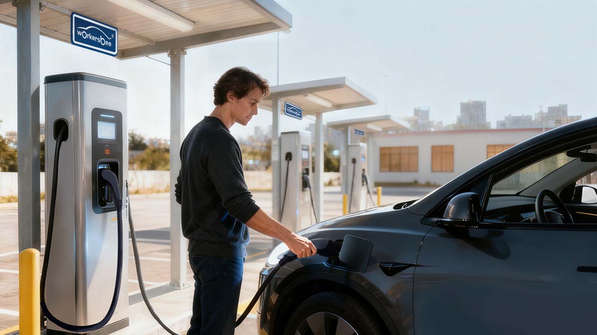
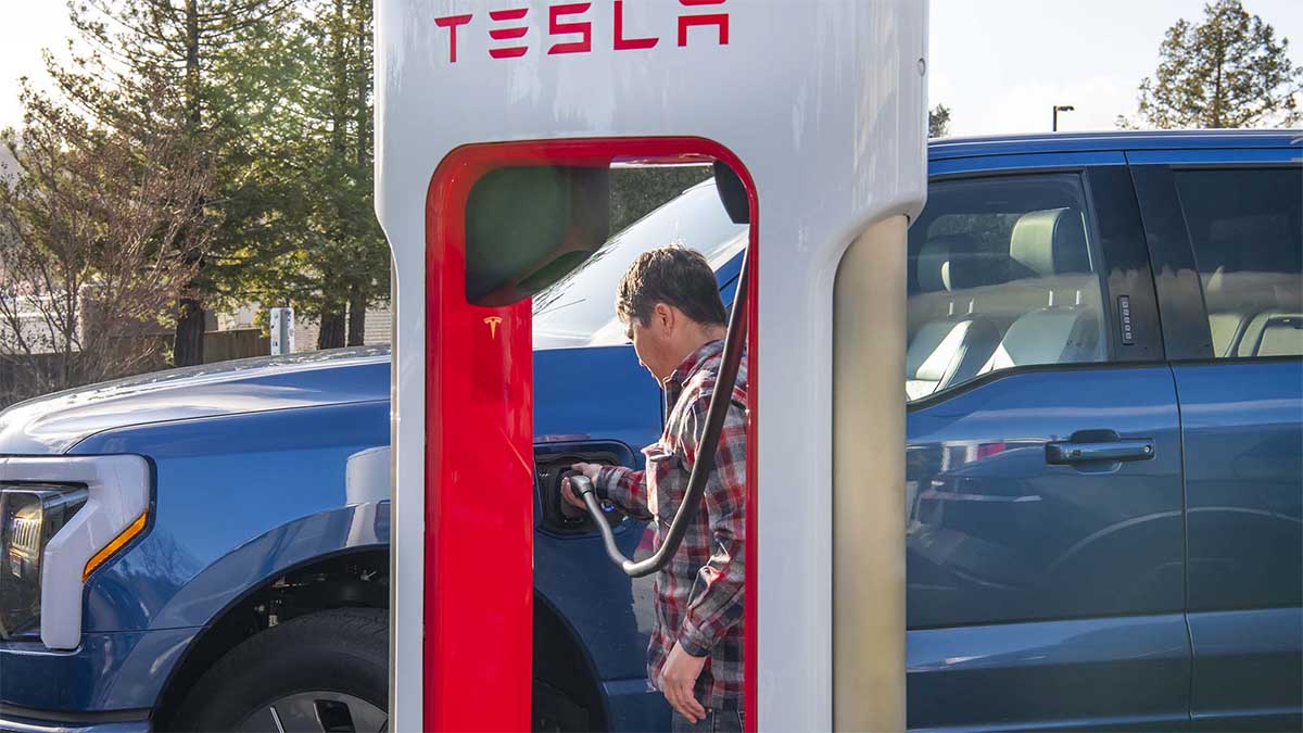
    As electric vehicles (EVs) become increasingly mainstream, the need for faster and more efficient charging solutions has become critical. Among the key components of this evolving infrastructure, EV connectors play a central role. With the rise of fast charging technologies, these connectors must evolve to support higher power levels and accommodate emerging standards. This article explores how fast charging is transforming EV connector design, the challenges manufacturers face, and the innovative solutions that are driving the future of EV charging infrastructure.     The Rapid Evolution of EV Charging Technologies 
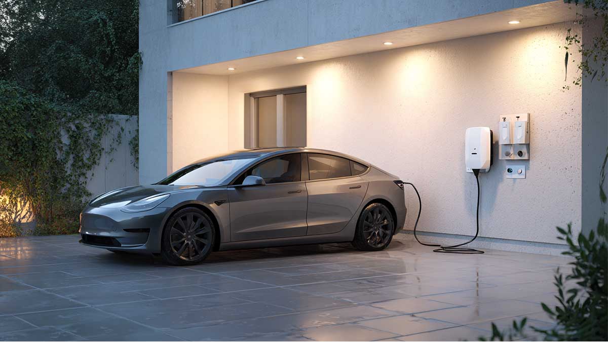
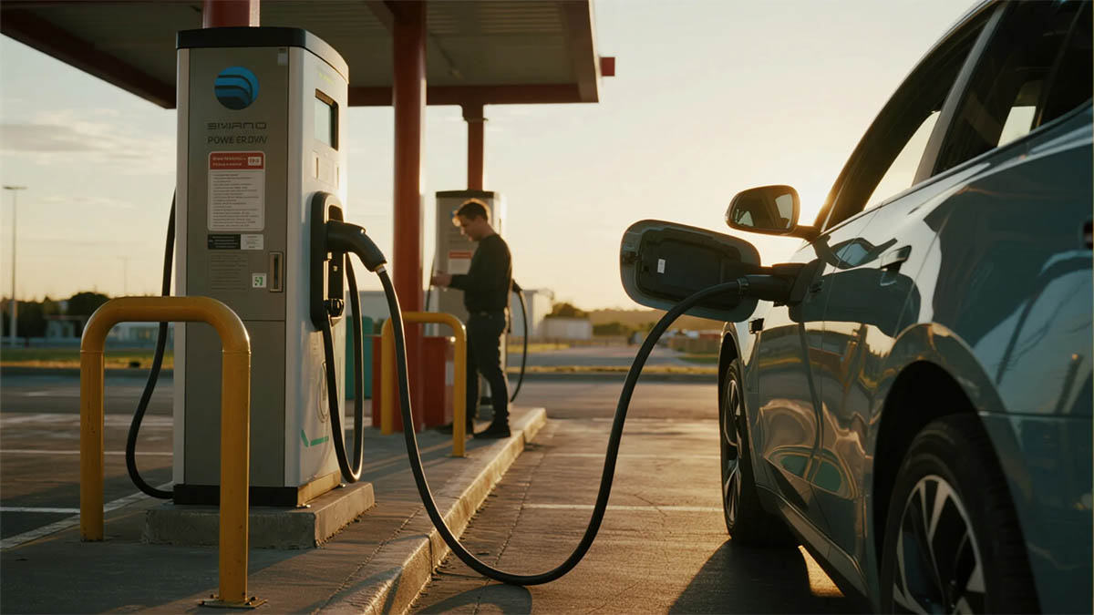
The charging process for electric vehicles has significantly evolved over the years. Early EV charging relied on Level 1 chargers (120V), which could take several hours to charge a vehicle. As demand for faster charging grew, Level 2 chargers (240V) emerged, reducing charge time significantly. Now, the shift to DC fast charging systems (Level 3) has transformed the charging landscape. Fast chargers can power an EV to 80% in under 30 minutes, making long-distance travel and daily commutes much more feasible.   However, fast charging comes with its own set of challenges, particularly in the design of the charging connectors. These connectors must support high power and voltage, handle heat generation, and ensure safety and durability—all while adhering to international standards.     Key Challenges in Designing Fast-Charging Connectors   1. Increased Power and Voltage Requirements Fast charging systems require connectors to handle higher power and voltage levels compared to standard chargers. Fast charging systems operate at voltages between 400V and 800V, with some pushing past 1000V in the future. This significant increase in voltage presents several challenges for connector design, including managing high electrical loads and ensuring the components do not overheat or degrade over time.   Advanced materials and innovative designs are required to manage these demands effectively. By reducing electrical resistance and using components that can withstand higher temperatures, manufacturers are developing high-voltage connectors that can handle the power surge associated with fast charging.   
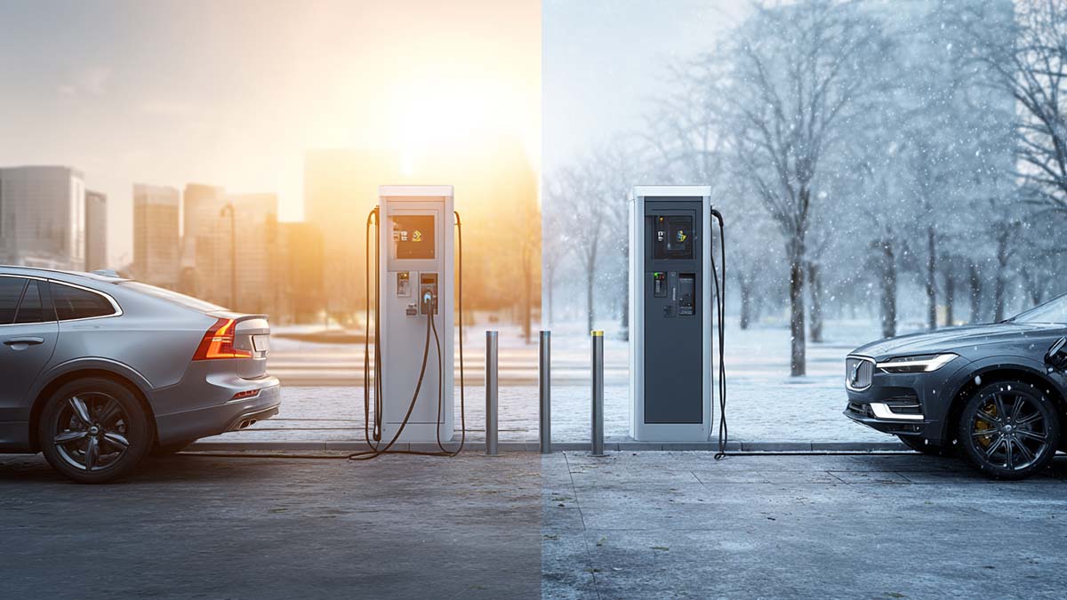
2. Effective Thermal Management 
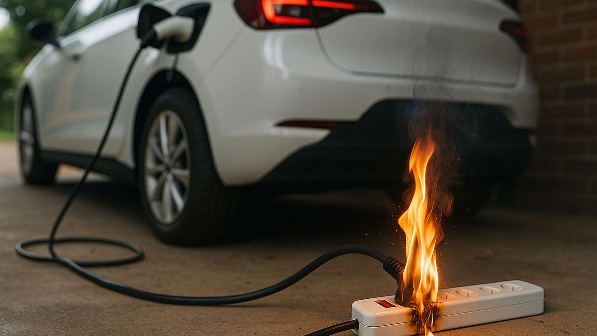
The faster an EV charges, the more heat is generated. This heat is a byproduct of the higher currents passing through the charging connectors and cables. Without proper thermal management, the connectors could fail prematurely, reducing their lifespan and potentially causing safety hazards such as overheating or fire.   To mitigate these risks, many manufacturers are investing in advanced cooling technologies and heat-resistant materials. Liquid-cooled connectors, for example, are increasingly being adopted to improve heat dissipation and ensure reliable performance during high-power charging.   
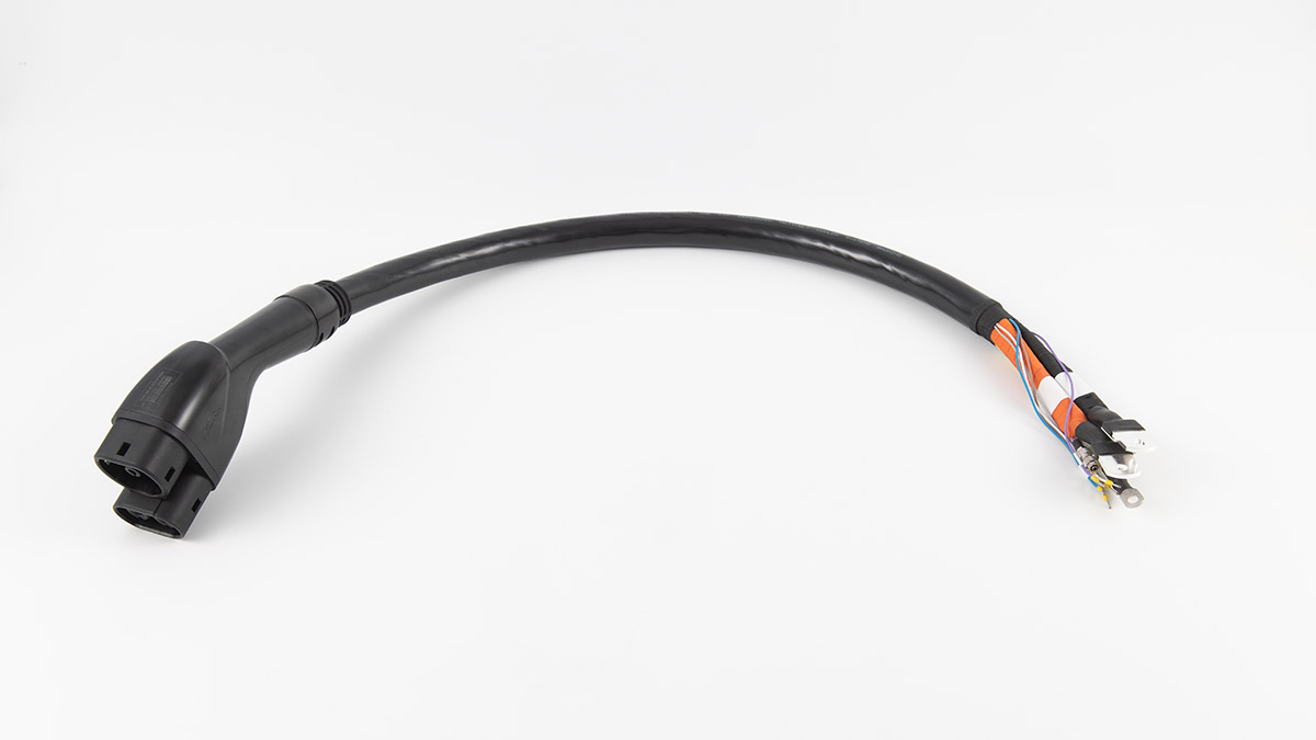
3. Durability and Longevity of Connectors Frequent use of charging stations, particularly in public charging areas, subjects connectors to wear and tear. Over time, repeated plugging and unplugging can cause mechanical degradation, affecting performance and connector integrity.   Designing connectors that can withstand these stresses is crucial. Manufacturers, like Workersbee, focus on enhancing durability through the use of corrosion-resistant materials and reinforced mechanical structures. These connectors are designed to perform reliably over years of heavy use, which is essential for widespread EV adoption.   4. Safety and Compliance with International Standards The high voltages and power associated with fast charging make safety a top priority. Fast charging connectors must incorporate high-voltage interlock (HVIL) systems to prevent electrical hazards such as electric shocks or short circuits. Additionally, connectors should meet global safety standards such as UL, CE, and RoHS to ensure they are safe for widespread use.   Workersbee connectors are designed with built-in overcurrent protection, automatic shutoff mechanisms, and temperature sensors to enhance safety. This ensures that fast charging is not only efficient but also safe for users, making it a viable option for public and private EV infrastructure.     Charging Time for 100% Charge at Different Levels The following chart compares the estimated time required for a full charge across different charging levels. As shown, Level 1 charging can take up to 8 hours, while DC Fast Charging can fully charge an EV in less than 30 minutes.     Charging Power at Different Charging Levels In the following chart, we compare the power output across various charging levels. Level 2 chargers provide up to 7.2 kW of power, while DC Fast Charging systems can reach 60 kW or more, significantly reducing charging time.       
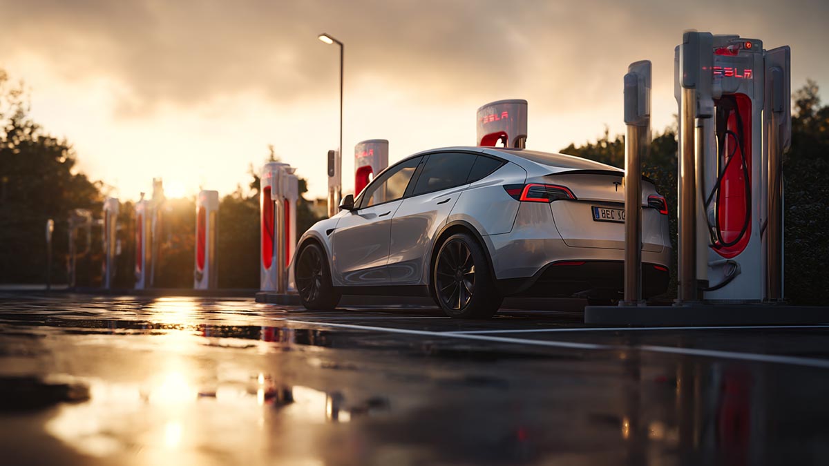
Global Standardization and the Future of EV Connectors The future of EV charging is closely tied to the standardization of charging connectors. As the demand for fast charging grows, it is essential to have connectors that meet international standards for compatibility and safety. Some of the most common standards today include CCS2 (Combined Charging System), CHAdeMO, and GB/T connectors.   These standards help facilitate compatibility between different EV models and charging stations, ensuring that drivers can charge their vehicles regardless of location. However, as charging speeds increase, new standards will be needed to accommodate next-generation fast chargers. The European Union, United States, and other regions are working on advancing connector standards that can support high-voltage and high-speed charging.   At Workersbee, we are committed to providing future-proof connectors that comply with both current and emerging standards. Our CCS2 and CHAdeMO compatible connectors are designed to meet the needs of today’s fast charging systems while being adaptable to future developments in the EV sector.     Why Workersbee Stands Out in EV Connector Design With over 17 years of experience in manufacturing EV connectors, Workersbee has built a reputation for providing reliable, high-quality solutions for fast-charging infrastructure. Our focus on innovation, sustainability, and safety has made us a trusted partner for global charging station operators.   1. Cutting-Edge Design and Technology Our advanced connector technology ensures that our products can handle high-voltage, high-power charging systems. Whether it’s CCS2 or NACS, our connectors are engineered to meet the demands of fast-charging systems, ensuring efficiency, safety, and reliability.   2. Global Compliance and Certifications We understand the importance of adhering to global safety and quality standards. Our products are certified with UL, CE, TUV, and RoHS, ensuring that they meet the highest safety, environmental, and performance benchmarks.   3. Sustainability and Eco-Friendly Materials As part of our commitment to sustainability, Workersbee uses eco-friendly materials in our connectors and continuously works to reduce the environmental impact of our manufacturing processes. Our products contribute to the transition toward cleaner and greener transportation solutions.   4. Comprehensive Support for Our Partners We offer end-to-end support to our partners, from product development and installation to after-sales service. Our team is dedicated to ensuring that every product we deliver provides the highest level of performance and satisfaction.     Conclusion Fast charging is transforming the EV landscape, and connectors are at the heart of this revolution. As the demand for quicker, more efficient charging grows, the design of connectors must evolve to meet the challenges of higher power, voltage, and safety. By focusing on innovation, reliability, and sustainability, Workersbee continues to lead the charge in providing cutting-edge solutions that support the future of EV charging infrastructure.   To learn more about our products and how we can help your EV charging needs, contact us today.  
    Read More
  • Do NACS to CCS adapters slow fast charging? Do NACS to CCS adapters slow fast charging?
    Sep 30, 2025
    More non-Tesla drivers are using Superchargers with a NACS to CCS adapter and wondering if that brick in the cable is choking speed. The short answer: with an approved, automaker-issued adapter, the adapter itself is rarely the bottleneck. What you see on the screen comes from the site hardware, your vehicle’s architecture, battery state of charge, and temperature. Get those right and an adapter won’t move the needle much.       Why the adapter usually isn’t the limitAutomaker adapters are designed to pass high current and high voltage with low resistance and good thermal paths. That means the limiting factor becomes the charger’s own ceiling and your car’s charge curve. At many sites the cabinet tops out around a set voltage and power; your car negotiates within that envelope. If your vehicle is a 400-V platform, you can often hit the normal peak you’d see on a same-brand DC fast charger. If you drive an 800-V car, you may bump into site-voltage limits on older hardware and see lower peaks, adapter or not.     What actually sets your speed• Charger version and limits. Cabinet power, maximum current, and maximum voltage define the top of your curve. Some locations also share power between paired posts, which can reduce peak power if both are busy.• Vehicle architecture. 400-V systems tend to align well with many sites’ voltage. 800-V systems need higher voltage to reach headline power, so older cabinets can cap them earlier. Preconditioning helps both cases.• Battery state and temperature. Arriving warm and low (roughly 10–30% state of charge) allows faster ramps. Cold packs, hot packs, and high state of charge all trigger taper no matter what hardware is in the middle.     When an adapter can slow things downNot all adapters are equal. Third-party units may carry lower current/voltage ratings or weaker thermal design, and some networks don’t allow them at all. Mechanical fit also matters: poor contact quality raises heat, and that can force the car or the site to pull back. If you see repeat early taper that isn’t tied to state of charge or temperature, inspect the adapter, the connector pins, and the way the cable is supported at the port.     Quick comparison: where a cap is likely Combo What to expect Why it happens 400-V EV + older high-power site Usually near normal peak Voltage aligns with the site 800-V EV + older high-power site Often lower peak than spec Site voltage ceiling, not the adapter 800-V EV + newest higher-voltage site Much better chance to meet the curve Higher voltage window available Third-party adapter + any site Highly variable; proceed with caution Ratings, thermals, and policy vary     How to get consistent real-world results• Use the official adapter for your brand and check its current/voltage rating.• Precondition the battery on the way; navigation to the site usually triggers it.• Aim to arrive between 10% and 30% state of charge for weekly top-ups.• Prefer newer, higher-voltage sites if you drive an 800-V EV.• Avoid back-to-back hot sessions; give the pack and hardware time to cool.• If the station pairs stalls, choose an unpaired post when possible.     FAQQ: Will an approved NACS↔CCS adapter cut my peak power?A: In normal use, no. With an automaker-issued adapter, speed is set by the site’s limits, your car’s charge curve, and battery conditions. The adapter’s job is to pass what both sides agree to deliver.   Q: Why is my 800-V car slower at some Superchargers?A: Older cabinets operate at lower maximum voltage. Your car can only take what the site can provide, so peak power drops even though the adapter is capable.   Q: Are third-party adapters okay to use?A: Only if they’re properly rated and accepted by the network you plan to use. Even then, mechanical fit and thermal performance matter. If the network disallows them, you may be blocked regardless of specifications.   Think of the adapter as a bridge, not a throttle. If you match your vehicle to the right site, arrive with a warm, low-SOC battery, and use approved hardware, you’ll see speeds determined by the charger and your pack—not by the adapter sitting between them.
    Read More
  • Why Mode 2 Charging Burns Power Strips and What to Do Instead Why Mode 2 Charging Burns Power Strips and What to Do Instead
    Sep 25, 2025
    What “Mode 2” actually isMode 2 is the portable charger that comes with many EVs: one end goes to a household outlet, the other to your car. It draws continuous current for hours—typically 8–16 A at ~230 V (about 1.8–3.7 kW). That “continuous for hours” part is the mismatch with many household accessories.     Why power strips get hot and fail Long, continuous load on parts designed for short burstsMost power strips and cheap extension leads are rated 10 A. They’re fine for a kettle for a few minutes—but not for a 6–10-hour continuous load. Even at 10 A, the strip’s internal bus bars and contacts keep heating.     1. Contact resistance = heatLoose sockets, tired springs, oxidation, dust, or a plug not fully seated all raise contact resistance. Power loss on those tiny points converts directly to heat. Heat carbonizes the plastic, springs get weaker, resistance rises again… a vicious cycle.   2. Thin conductors and weak jointsBudget strips use thin copper and riveted joints. Add a long lead with 0.75–1.0 mm² conductors and you get voltage drop and extra heating along the cable run.   3. Daisy-chaining adaptersUniversal adapters, travel plugs, multi-layer converters—all add more contacts and more heat points. One weak link is enough to char the stack.   4. Poor heat dissipationCoiled or bundled cable acts like an insulator. Put that on a carpet or behind curtains in summer and the temperature climbs.   5. Shared loadsIf that same strip also feeds a heater, microwave, or PC, the total current can exceed what the strip and the wall outlet can safely carry.   6. Aging or undersized house wiringOld circuits on small breakers, loose terminal screws, weak wall sockets, or bad earthing can start heating inside the wall—out of sight.   7. Micro-arcs from movementA plug that wiggles even slightly under load will arc. Each arc pits the metal, raising resistance and heat the next minute.     Numbers that make it real• 10 A × 230 V ≈ 2.3 kW, for hours.• 16 A × 230 V ≈ 3.7 kW, for hours. A typical “10 A/250 V” power strip was never intended to carry that kind of continuous power for an entire night.     How to charge safely at home (practical checklist)• Don’t use a power strip. Plug the Mode 2 charger directly into a wall outlet.• Prefer a dedicated circuit. 16–20 A breaker, 30 mA RCD/RCBO, copper wiring ≥ 2.5 mm², properly tightened terminals.• Use a quality outlet. Full-depth, firm grip, heat-resistant housing. Replace old or loose sockets.• Limit current when in doubt. If your portable charger lets you choose 8/10/13/16 A, start low (8–10 A) on older wiring or hot days.• No adapters or daisy chains. Avoid travel converters or “universal” sockets; every extra contact is a heat spot.• Lay the cable out straight. Don’t coil it. Keep it off carpets, bedding, or piles of clothes.• Do a warm-check after 30–60 minutes. The plug and outlet should feel only mildly warm. If it’s hot to the touch or smells “toasty,” stop and inspect.• Keep the area ventilated and dry. Moisture and dust increase tracking and arcing risks.• Consider a wallbox (Mode 3). A fixed EVSE with the correct breaker, RCD, and wiring is inherently safer and usually faster.     Quick “symptom → meaning → action” guide What you notice What it likely means What to do next Plug/outlet too hot to touch High contact resistance or overload Stop charging, let it cool, replace outlet, reduce current Brown/yellow plastic, scorch marks Past overheating, carbonization Replace outlet and plug; check wiring torque Crackling/popping sounds Micro-arcing at loose contacts Stop immediately; repair/replace hardware Charger trips RCD intermittently Leakage or dampness; wiring issue Dry the area, inspect cable, have an electrician test Voltage drops (lights dim) Long run, thin cable, loose joints Shorten the run, upsize wiring, tighten terminals Cable feels hot while coiled Self-heating with poor cooling Uncoil fully and elevate off insulating surfaces     FAQIs a 10 A power strip “OK if it’s within rating”?Not for EVs. That rating assumes intermittent household use, not many hours at the edge. Continuous duty cooks weak links inside strips.   If I install a 16 A outlet, is it guaranteed safe?Only if the entire chain is right: correct breaker and RCD, proper wire gauge, tight terminations, quality outlet, and sensible ambient temperatures.   What current should I set on my portable charger?Use the lowest that still meets your schedule on older circuits (8–10 A). If you know you have a dedicated 16–20 A circuit with good wiring and a robust outlet, 13–16 A can be appropriate.   Can I use a heavy-duty extension lead?If you must, choose a single, short, heavy-duty lead with ≥ 1.5–2.5 mm² conductors, fully uncoiled, with a snug, weather-rated connector. Even then, a direct wall outlet is better.   Why does a plug sometimes smell even when it looks fine?Heat can bake plasticizers and dust before you see discoloration. Smell is an early warning—stop and investigate.   What’s the role of the RCD/RCBO?A 30 mA device trips on leakage to protect people from shock. It doesn’t prevent overheating from poor contacts—that’s why mechanical quality and proper wiring still matter.   When should I move to a wallbox?If you charge most nights, need higher currents, or your house wiring is older. The cost buys you dedicated protection, better connectors, and less stress on outlets.     A simple decision path• You charge occasionally, short sessions, new wiring: Mode 2 to a quality wall outlet can be acceptable—avoid strips, keep current low, and monitor temperature.• You charge often or overnight, or wiring is older: install a proper wallbox on a dedicated circuit.• Anything feels hot, smells odd, or trips repeatedly: stop, fix the root cause, then resume.   EVs are continuous loads. Power strips aren’t built for that. Use a direct wall outlet on a solid circuit, keep connections clean and firm, limit current when uncertain, and move to a dedicated wallbox if charging becomes routine.
    Read More
  • How Many Amps Does a Home EV Charger Need? (Europe) How Many Amps Does a Home EV Charger Need? (Europe)
    Sep 24, 2025
    Short answer: decide first between single-phase 230 V and three-phase 400 V. For most homes, 7.4 kW (32 A, single-phase) is the sweet spot. If you have a three-phase supply and approval, 11 kW (16 A × 3) is widely practical; 22 kW (32 A × 3) is site-dependent and often needs notification or limits from your DSO/DNO.     What amps really change Amperage sets the charging speed and installation complexity. Three-phase spreads current across phases, reducing per-conductor load and keeping cables manageable.     Your real-world constraints   Supply type: many homes are single-phase; three-phase opens the door to 11–22 kW.   Main fuse / contracted capacity: your DSO/DNO may cap available current.   Onboard charger (OBC): many EVs accept 7.4 kW (1×32 A) or 11 kW (3×16 A); fewer make full use of 22 kW (3×32 A).   Local regulations: notification/approval thresholds and load management rules differ by country.     Common EU charging tiers 3.7 kW = 1×16 A; 7.4 kW = 1×32 A; 11 kW = 3×16 A; 22 kW = 3×32 A.     What to pick and when • 1×32 A (7.4 kW): default for single-phase homes—fast enough overnight without stressing the main fuse. • 3×16 A (11 kW): balanced three-phase choice; many EVs top out here on AC. • 3×32 A (22 kW): only if your car and contract allow it, and cable runs and switchgear are sized accordingly.   Cost levers you feel Run length, cable cross-section, protection devices (RCD type/RCBO), and whether load management is needed alongside heat pumps or induction hobs.   A 30-second decision path   Confirm single-phase vs three-phase supply and contracted capacity.   Check your car’s OBC (7.4 vs 11 vs 22 kW).   Pick 7.4 kW (1×32 A) for most single-phase homes; 11 kW (3×16 A) for most three-phase homes.   Use load management if the main fuse is modest or you plan multiple EVs.   If capacity is tight or you switch between locations, a Portable EV Charger (Type 2) with adjustable current ensures a safe and adaptable setup. Pair it with an EV Charging Gun Holster & Cable Dock to protect the connector and keep cables tidy day to day.     Installer checklist • Confirm supply and main fuse • Select breaker and cable cross-section for 1φ/3φ tier • RCD type per EVSE spec • Labeling, torque, and functional test • Configure load management where required     FAQ  Do I need a three-phase charger to charge fast at home? Not necessarily. 7.4 kW (1×32 A) on single-phase covers most overnight needs. Three-phase helps if you want 11 kW (3×16 A), have higher daily mileage, or need to balance loads across phases.   Is 22 kW (3×32 A) worth it? Only if your car supports 22 kW AC, your contracted capacity and switchgear allow it, and run lengths/cable cross-sections are sized accordingly. Otherwise, you pay more for infrastructure with little real-world gain.   Which RCD/protection do I need for my wallbox? Follow the EVSE spec and local rules. Many units integrate 6 mA DC detection, allowing an upstream Type A device; others require Type B. Your installer will size the breaker, RCD/RCBO, and cable cross-section per 1φ/3φ tier and national code.
    Read More
  • Why High-Power CCS2 Sites Move to Liquid-Cooled Connectors Why High-Power CCS2 Sites Move to Liquid-Cooled Connectors
    Sep 22, 2025
    High current changes everything. Once a CCS2 site aims beyond the mid-300-amp range for long stretches, heat, cable weight, and driver ergonomics become the real constraints. Liquid-cooled connectors move heat out of the contact and cable core so the handle stays usable and power stays up. This guide explains when the switch makes sense, what to look for in the hardware, and how to run it with low downtime.     What really breaks at high current– I²R loss drives temperature at contacts and along the conductor.– Thicker copper reduces resistance but makes the cable heavy and stiff.– Ambient heat and back-to-back sessions stack; afternoon queues push shells past limits.– When the connector overheats, the controller derates; sessions stretch and bays back up.     Where natural cooling still winsNaturally cooled handles work well for moderate power and cooler climates. They avoid pumps and coolant. Service is simpler and spares are cheaper. The trade-off is sustained current in hot seasons or under heavy duty.     How liquid cooling solves the problemA liquid-cooled CCS2 connector routes coolant close to the contact set and through the cable core. Heat leaves the copper, not the driver’s hand. Typical assemblies add temperature sensing on power pins and in the cable, plus flow/pressure monitoring and leak detection tied to safe shutdown.     Decision matrix: when to move to liquid-cooled CCS2 Target current (continuous) Typical use case Cable handling & ergonomics Thermal margin across the day Cooling choice ≤250 A Urban fast chargers, low dwell Light, easy High in most climates Natural 250–350 A Mixed traffic, moderate turnover Manageable but thicker Medium; watch hot seasons Natural or Liquid (depends on climate/duty) 350–450 A Highway hubs, long dwell, hot summers Heavy if natural; fatigue rises Low without cooling; early derating Liquid-cooled ≥500 A Flagship bays, fleet lanes, peak events Needs slim, flexible cable Requires active heat removal Liquid-cooled     Workersbee CCS2 liquid-cooled at a glance– Current classes: 300 A / 400 A / 500 A continuous, up to 1000 V DC.– Temperature rise target: < 50 K at the terminal under stated test conditions.– Cooling loop: typical 1.5–3.0 L/min flow at about 3.5–8 bar; around 2.5 L coolant for a 5 m cable.– Heat extraction reference: about 170 W @300 A, 255 W @400 A, 374 W @500 A (published data supports engineering of higher-amp scenarios).– Environmental: IP55 sealing; operating range −30 °C to +50 °C; acoustic output at the handle under 60 dB.– Mechanics: mating force under 100 N; mechanism tested for more than 10,000 cycles.– Materials: silver-plated copper terminals; durable thermoplastic housings and TPU cable.– Compliance: designed for CCS2 EVSE systems and IEC 62196-3 requirements; TÜV/CE.– Warranty: 24 months; OEM/ODM options and common cable lengths available.     Why drivers and operators feel the difference– Slimmer outer diameter and lower bend resistance improve reach to ports on SUVs, vans, and trucks.– Cooler shell temperatures reduce re-plugs and failed starts.– Extra thermal headroom keeps set power flatter during afternoon peaks.   Reliability and service, kept simpleLiquid cooling adds pumps, seals, and sensors, but design choices keep downtime low. Workersbee focuses on field-swappable wear parts (seals, trigger modules, protective boots), accessible temperature and coolant sensors, clear leak-before-break paths, and documented torque steps. Techs can work quickly without pulling the whole harness. A two-year warranty and >10k mating-cycle design align with public-site duty.     Commissioning notes for high-power bays Commission the hottest bay first. Map contact and cable-core sensors; calibrate offsets. Stage holds at 200 A, 300 A, and target current; record ΔT from ambient to handle shell. Set current-versus-coolant curves and boost windows in the controller; enable graceful taper. Monitor three numbers: contact temperature, cable inlet temperature, and flow. Alert policy: “yellow” for drift (rising ΔT at the same current), “red” for no-flow, leak, or over-temp. On-site kit: pre-filled coolant pack, O-rings, trigger module, sensor pair, torque sheet. Weekly review: plot power hold time vs ambient; rotate bays if one lane heats earliest.     Buyer scorecard for CCS2 liquid-cooled connectors Attribute Why it matters What good looks like Continuous current rating Drives session time Holds target amps for an hour in hot weather Boost behavior Peaks need control and recovery Stated boost time plus auto-recovery window Cable diameter & mass Ergonomics and reach Slim, flexible, true one-hand plug-in Temperature sensing Protects contacts and plastics Sensors on pins and in cable core Coolant monitoring Safety and uptime Flow + pressure + leak detect + interlocks Serviceability Mean time to repair Swap seals, triggers, and sensors in minutes Environmental sealing Weather and washdowns IP55 class with tested drain paths Documentation Field speed and repeatability Illustrated torque steps and spares list     Thermal reality checkTwo conditions stress even good hardware: high ambient temperature and high duty cycle. Without liquid cooling, the controller must derate earlier to protect contacts. Using a liquid-cooled CCS2 handle lets the site sustain target current for longer, trimming queues and stabilizing per-bay revenue.   Human factorsDrivers judge a site by how quickly they can plug in and walk away. A stiff cable or hot shell slows them down and raises error rates. Slim, liquid-cooled cables make ports easier to reach and allow a natural, comfortable plug-in angle.   Compatibility and standardsThe CCS2 signaling stays the same; what changes is the heat path and the monitoring. Build acceptance around temperature rise, shell temperature, and fault handling. Keep per-bay records of current, ambient, contact temperature, and taper points to support audits and seasonal tuning.   Cost of ownership, not just CapExFrequent derating costs more in longer sessions and walk-offs than it saves on hardware. Factor session time at your top ambient bins, tech time for common swaps, consumables (coolant, filters if used), and unplanned downtime hours per quarter. For high-duty hubs, liquid-cooled connectors win on throughput and predictability.     Where Workersbee fits Workersbee’s liquid-cooled CCS2 handle is built for steady high current and easy upkeep, with field-accessible sensors, quick-swap seals, a quiet grip, and clear torque steps for technicians. Integration notes cover flow (1.5–3.0 L/min), pressure (about 3.5–8 bar), power draw under 160 W for the cooling loop, and typical coolant volume per cable length. This helps sites bring flagship bays online quickly and hold power in hot seasons without moving to bulky cables.     FAQ At what current should I consider liquid cooling?When your plan calls for sustained current in the upper-300-amp range or higher, or when your climate and duty cycle push shell temperatures up. Is liquid cooling hard to maintain?It adds parts, but good designs make the usual swaps quick. Keep a small kit on site and log thresholds. Will drivers notice the difference?Yes. Slimmer cables and cooler handles make plug-ins faster and reduce mis-starts. Can I mix bays?Yes. Many sites run a few liquid-cooled lanes for heavy traffic and keep naturally cooled lanes for moderate demand.
    Read More
  • Should I Charge My EV to 100%? Should I Charge My EV to 100%?
    Sep 17, 2025
    Most days you do not need a full battery. Set a daily limit and use 100% only when the extra range is useful. Finish charging close to the time you leave so the car does not sit at full for hours.   Why this works is simple. Fast charging is quickest when the battery is low to mid. Near the top, the car slows the power to protect the pack. Those last few percent take the longest and add the most heat. Heat plus high state of charge for a long time is what you want to avoid.   Related Reading: Why EV Charging Slows After 80%?   Not every battery is the same. Many cars use NMC or NCA cells. They do well when you keep daily limits a bit lower. Some cars use LFP cells. LFP can live with higher limits in daily use, but it does not like long hot parking at 100% either. If you are not sure which one you have, follow the charge limit the vehicle app suggests.   Think about your week. For commuting, pick a number and stick to it. Eighty percent is a good start. You leave home with a cushion, reach work without worry, and get back with room to spare. At home, top up again. Small, frequent charges are fine and save time. If your route is short, set the limit even lower and see if your day still feels easy.   Trip days are different. The night before you go, raise the limit to 100%. Use the schedule in your app so charging finishes just before you depart. If you need to stop on the road, do short, efficient sessions. Arrive low, leave near 70–85%, and drive on. You will spend less time per stop than chasing the very top of the battery.     Cold days need a small tweak. Tell the car when you plan to leave so it can warm the battery. That keeps regen stronger and charging smoother. Try not to park for long with 0–10% in freezing weather. Give yourself a little buffer before you shut down for the night.     A tiny table you can keep in mind: Battery type Daily limit (typical) Use 100% for NMC / NCA about 70–90% trips, winter, or sparse chargers; finish near departure LFP up to 100% if the maker recommends it same as above; avoid long hot parking at full     You also care about the plug. Heavy cables and awkward angles waste time and energy. Sites that use ergonomic, serviceable handles make it easier to plug in and go. Workersbee DC connectors focus on grip shape and clear service steps, which helps keep sessions steady for drivers and reduces downtime for site owners. If a handle ever feels loose, damaged, or unusually hot, stop the session and tell the host. A quick check is better than a bad charge.   Storing the car for a while? Aim for roughly 50–60%. Park in a cool place if you can. Many cars offer a storage or battery care mode. Turn it on and let the car manage itself. Check once if the break is long. You do not need to micromanage it every day.     A simple three-step setup you can do once:Step 1: Open the vehicle app and set a daily charge limit. Start with 80%.Step 2: Turn on a schedule or departure time so charging ends close to when you leave.Step 3: On trip nights or very cold nights, raise the limit to 100% and keep the “finish by” time near your departure.     You will hear strong opinions about fast charging. Occasional fast sessions are fine. The car manages current and temperature. What hurts most is heat and time at either extreme. Try not to sit at 100% in the sun. Try not to leave the pack near empty for long. Keep your habits simple and regular.   What if you only use public chargers? End the session when you have enough to reach your next stop with a cushion. That could be 70%, 80%, or any number that fits your route. The top of the battery is slow everywhere, not just at one brand of station. Moving on sooner frees the stall for the next driver and saves your own schedule.   Hardware with good sensing and thermal design helps here too. Workersbee temperature-sensing connectors support clear heat control at the handle, which keeps charge power stable across the session.     You are not chasing a perfect 100% every day. You are chasing a day that runs on time. Set a sensible limit, raise it when a trip calls for it, and let the car handle the rest. With a few simple settings, charging becomes quiet background work, and driving takes the lead.
    Read More
  • How to Upgrade Existing Chargers to Support New Connectors How to Upgrade Existing Chargers to Support New Connectors
    Sep 16, 2025
    Standards evolve, vehicles change, and sites can’t stand still. The good news: many DC fast chargers can add newer connectors without starting from zero—if you line up electrical headroom, signal integrity, software, and compliance in the right order.     Industry snapshot (dated milestones that shape upgrades) SAE moved the North American connector from an idea to a documented target: a technical information report in December 2023, a Recommended Practice in 2024, and a dimensional spec for the connector and inlet in May 2025.   Major networks have publicly said they’ll offer the new connector at existing and future stations by 2025, while equipment makers shipped conversion kits for existing DC fast chargers as early as November 2023. Separately, one network reported its first pilot site with native J3400/NACS connectors in February 2025, adding a second in June 2025. Some Superchargers are open to non-Tesla EVs when the car has a J3400/NACS port or a compatible DC adapter.   What this means for you: plan for dual-connector coverage where traffic is mixed, and treat cable-and-handle swaps as the first option when your cabinet’s electrical, thermal, and protocol limits already fit the new duty.   Upgrade paths (pick the lightest that works) Cable-and-handle swap: replace the lead set with the new connector while keeping cabinet/power modules. Lead + sensor harness refresh: Add temperature sensing at the pins, tidy the HVIL circuit, and reinforce shielding/ground continuity so the data channel stays stable and thermal derating unfolds smoothly. Dual-connector add: keep CCS for incumbents and add J3400 for new traffic. Cabinet refresh: step up only if voltage/current class or cooling is the real blocker.     Retrofit flow (from idea to live energy) Map vehicles to support (voltage window, target current, cable reach). Check cabinet headroom (DC bus & contactor ratings, isolation-monitor margin, pre-charge behavior). Thermals (air vs liquid; sensor placement at the hottest elements). Signal integrity (shield continuity, clean grounds, HVIL routing). Protocols (ISO 15118 plus legacy stacks; plan contract certificates if offering Plug & Charge). CSMS & UI (connector IDs, price mapping, receipts, on-screen prompts). Compliance (labels, program rules; keep a per-stall change record). Field plan (spare kits, minutes-level swap procedures, acceptance tests, rollback).     Engineering noteHandshake stability lives inside the handle and lead as much as in firmware. Stable contact resistance, verified shield continuity, and clean grounds protect the data channel that rides on the power lines. As practical reference points, assemblies such as Workersbee high-current DC handle embed temperature sensing at hot spots and maintain continuous shield paths so current steps are smooth rather than abrupt.   Can I just swap the cable and handle? Often yes—when the cabinet’s bus window, contactors, pre-charge, cooling, shield/ground continuity, and protocol stacks already meet the new duty. Where you must keep CCS available or the cabinet wasn’t built for retrofits, use dual leads or stage conversions by bay.     Five bench checks before field work Bus & contactors: ratings meet or exceed the new connector’s voltage/current duty. Pre-charge: resistor value and timing handle the vehicle inlet capacitance without nuisance trips. Thermals: cooling path has margin; pin-temperature sensing is in the right place (near the hottest elements). Signal integrity: shield continuity and low-impedance drains end-to-end; clean grounds. Protocol stacks: ISO 15118/Plug & Charge where needed; certificate handling planned.     Retrofit readiness scorecard Dimension Why it matters Pass looks like What to check Bus & contactors Safe close/open at target duty Ratings ≥ new duty; thermal margin intact Nameplate + type tests Isolation & pre-charge Avoid nuisance trips on inrush Stable pre-charge across models Log plug-in → pre-charge separately Thermal path Predictable current steps, not hard cuts Sensors at hot spots; proven cooling path Thermal logs during soak Signal integrity Clean handshake beside high current Continuous shield & ground; low noise Continuity tests; weather-band trials Serviceability Short incidents, fast recovery Labeled spares; no special tools Swap order: handle → cable → terminal UI & CSMS Fewer support calls Clear prompts; consistent IDs & receipts Price and contract mapping tests Compliance Avoid re-inspection surprises Labels and paperwork aligned Per-stall change record   Field-proven acceptance tests Cold start: first session after overnight; log plug-in → pre-charge and pre-charge → first amp as two metrics. Wet handle: light exterior spray (no flooding); confirm clean handshake. Hot soak: After sustained operation, confirm the charger reduces current in controlled steps rather than with abrupt cutoffs. Longest lead bay: confirm voltage drop and on-screen messaging. Reseat: single unplug/replug; recovery should be quick and clean.     FAQs Can existing DC fast chargers be upgraded to new connectors?Yes in many cases—starting with a cable-and-handle swap when electrical, thermal, and protocol checks pass. Some vendors provide retrofit options; others recommend new builds for units not designed for retrofits.   Will we alienate CCS drivers if we add J3400?Keep dual connectors during the transition. Several networks have committed to adding J3400/NACS while retaining CCS.   Do we need software changes?Yes. Update connector IDs, price logic, certificate handling, and UI messages so receipts and reports stay consistent.   Is ISO 15118 required for new connectors?Not universally, but it enables contract-at-the-cable and structured power negotiation, and pairs well with J3400 rollouts.   Upgrades succeed when mechanics, firmware, and operations move together. Do the lightest change that delivers a clean start and a predictable ramp—then make that swap repeatable across bays.
    Read More
  • Why EV Charging Slows After 80% Why EV Charging Slows After 80%
    Sep 15, 2025
    The short answerCharging slows after roughly 80 percent because the car protects the battery. As cells fill up, the BMS shifts from constant current to constant voltage and trims the current. Power tapers, and each extra percent takes longer. This is normal behavior.   Related articles: How to Improve EV Charging Speed (2025 Guide)     Why the taper happens Voltage headroomNear full, cell voltage approaches safe limits. The BMS eases current so no cell overshoots. Heat and safetyHigh current makes heat in the pack, cable, and contacts. With less thermal margin near full, the system reduces power. Cell balancingPacks have many cells. Small differences grow near 100 percent. The BMS slows down so weaker cells can catch up.     What drivers can do to save time• Set the fast charger in the car’s navigation to trigger preconditioning.• Arrive low, leave early. Reach the site around 10–30 percent, charge to the range you need, often 70–80 percent.• Avoid paired or busy stalls if the site shares cabinet power.• Check the handle and cable. If they look damaged or feel very hot, switch stalls.• If a session ramps poorly, stop and start on another stall.   When going past 80 percent makes sense• Long gap to the next charger.• Very cold night and you want a buffer.• Towing or long climbs ahead.• The next site is limited or often full.     How sites influence the last 20 percent• Power allocation. Dynamic sharing lets an active stall take full output.• Thermal design. Shade, airflow, and clean filters help stalls hold power in summer.• Firmware and logs. Current software and trend checks prevent early derates.• Maintenance. Clean pins, healthy seals, and good strain relief lower contact resistance.     Tech note — Workersbee On high-use DC lanes, the connector and cable decide how long you can stay near peak. Workersbee’s liquid-cooled CCS2 handle routes heat away from the contacts and places temperature and pressure sensors where a technician can read them fast. Field-replaceable seals and clear torque steps make swaps quick. The result is fewer early trims during hot, busy hours.     Quick diagnostic flow Step 1 — Car• SoC already high (≥80 percent)? Taper is expected.• Battery cold or hot message? Precondition or cool, then retry. Step 2 — Stall• Paired stall with a neighbor active? Move to a non-paired or idle stall.• Handle or cable very hot, or visibly worn? Switch stalls and report it. Step 3 — Site• Hub packed and lights cycling? Expect reduced rates or route to the next site.     80%+ behavior and what to do Symptom at 80–100% Likely cause Quick move What to expect Sharp drop near ~80% CC→CV transition; balancing Stop at 75–85% if time matters Quicker trips with two short stops Hot day, early trims Thermal limits in cable/charger Try shaded or idle stall More stable power Two cars share one cabinet Power sharing Pick a non-paired stall Higher and steadier kW Slow start, then taper No preconditioning Set charger in nav; drive a bit longer before stop Higher initial kW next try Good start, repeated dips Contact or cable issue Change stalls; report handle Normal curve returns      FAQ Q1: Is slow charging after 80% a charger fault?A: Usually not. The car’s BMS tapers current near full to protect the battery. That said, you can rule out a bad stall in under two minutes:• If you’re already above ~80%, a falling power line is expected—move on when you have enough range.• If you’re well below ~80% and power is abnormally low, try an idle, non-paired stall. If the new stall is much faster, the first one likely had sharing or wear issues.• Visible damage, very hot handles, or repeated session drops point to a hardware problem—switch stalls and report it.   Q2: When should I charge past 90%?A: When the next stretch demands it. Use this simple check:• Look at your nav’s energy-at-arrival for the next charger or your destination.• If the estimate is under ~15–20% buffer (bad weather, hills, night driving, or towing), keep charging past 80%.• Sparse networks, winter nights, long climbs, and towing are the common cases where 90–100% saves stress.   Q3: Why do two cars on one cabinet both slow down?A: Many sites split one power module between two posts (paired stalls). When both are active, each gets a slice, so both see lower kW. How to spot it and fix it:• Look for paired labels (A/B or 1/2) on the same cabinet, or for signage explaining sharing.• If your neighbor plugs in and your power falls, you’re likely sharing. Move to a non-paired or idle post.• Some hubs have independent cabinets per post; in those cases, pairing isn’t the cause—check temperature or the stall’s condition instead.   Q4: Do cables and connectors really change my speed?A: They don’t raise your car’s peak, but they decide how long you can stay near it. Heat and contact resistance trigger early derates. What to watch:• Signs of trouble: a handle that’s very hot to the touch, scuffed pins, torn seals, or a cable that kinks sharply.• Quick fixes for drivers: pick a shaded or idle stall, avoid tight bends, and switch posts if the handle feels overheated.• Site practices that help everyone: keep filters clear and air moving, clean contacts, replace worn seals, and use liquid-cooled cables on high-traffic, high-power lanes to hold current longer.
    Read More
  • The Role of ISO 15118 in EV Connector Communication (2025) The Role of ISO 15118 in EV Connector Communication (2025)
    Sep 11, 2025
    You plug in, the screen wakes, and energy starts to move. In those first seconds the vehicle and the charger agree on identity, limits, and safety. ISO 15118 provides the shared protocol that lets the car and charger agree on the terms of a session. It sits above the metal and seals inside the connector, turning a mechanical mate into a predictable digital exchange.     What ISO 15118 actually doesISO 15118 defines the messages and timings an EV and a charging system use during a session. It covers capability discovery, contract-based authentication, pricing and schedule updates, and how both sides should respond to faults. With a shared protocol, a car can authenticate at the cable, a site can shape power in real time, and logs can be tied to vehicles rather than swipe cards.   How data rides through a physical connectorThe same assembly that carries hundreds of amps also carries a narrowband data signal. In most public DC systems outside China, that signal rides on the power conductors while dedicated pins confirm presence and allow high-voltage contactors to close. Stable contact resistance, shield continuity, and clean ground paths keep the channel intact. When any of those slip, the station shows a “communication” fault even though the root cause is mechanical or environmental.   Plug & Charge—what changes at the startPlug & Charge uses certificates so the vehicle can present its contract at the moment of insertion. The charger checks that contract and starts the session without cards or apps. Sites see shorter queues and fewer support calls. Fleet operators get charging records mapped to vehicle asset IDs, making cost allocation and audits straightforward.   Smart power, scheduling, and bidirectional readinessBeyond a basic current cap, ISO 15118 supports negotiated power ceilings, scheduling windows, and contingency rules when conditions change. Depots can smooth peaks and schedule topping sessions across a shift. Highway sites can share limited capacity across many bays with predictable ramps instead of abrupt cuts. The same building blocks prepare hardware and software for wider vehicle-to-grid use as markets mature.     From plug-in to power-on: how a charging session unfolds Handle seats and locks; proximity and presence circuits confirm a safe mate. A communication link forms; roles are set and capabilities exchanged. Identity is presented; if enabled, a contract is verified at the cable. Limits are agreed: voltage window, current ceiling, ramp profile, thermal plan. The charger aligns bus voltage and closes contactors under supervision. Current ramps to the profile while both sides monitor and adjust. The session stops; current ramps down, contactors open, and a receipt is recorded.     Buyer and operator scorecard Dimension What it looks like on site Why it matters What to ask vendors for Handshake reliability First-try starts during peak hours Fewer queues and retries Success rates by temperature and humidity bands Time to first kWh Seconds from plug-in to energy Real throughput, not just nameplate power Distribution data and acceptance targets Plug & Charge readiness Contract at the cable, no cards or apps Shorter lines, cleaner logs Certificate lifecycle tooling and renewal process Thermal derating clarity Predictable current steps as heat rises Driver trust and reliable ETAs Pin-temperature sensing and on-screen messaging behavior EMC discipline Stable comms next to high current Fewer “phantom” protocol faults Shielding/ground design and continuity test results Serviceability Minutes-level swaps for handles and cables Lower downtime and callout costs MTTR targets, labeled parts, video procedures Lifecycle documentation Limits, inspection cadence, failure modes in simple terms Safer, repeatable operations across shifts Maintenance schedule and acceptance tests     Engineering notesTreat shielding and ground as first-class design elements. Verify shield continuity across the full assembly and route drains with low-impedance terminations. Place temperature sensors close to the hottest elements so current steps are smooth rather than abrupt. As a practical reference point, some high-current DC handles—such as Workersbee high-current DC handle—embed sensing near hot spots and maintain continuous shield paths from handle to cabinet. These choices reduce “mystery” faults in busy windows.     Field observationsMost handshake retries show up on chilly mornings, with damp connectors, and during hot, sun-soaked afternoons. Condensation inside cavities and loose ground lugs inject noise into the data channel. Balancing sealing and venting, adding a quick torque check to the inspection routine, and routing cables to avoid sharp bends cut retries sharply. Assemblies with verified shield continuity and grounding—e.g., Workersbee ISO 15118-ready connector assemblies—help keep the data path quiet when current and heat are high.     Implementation details you can verify• Every build lot should include checks for shield continuity and ground resistance, plus a temperature-rise spot test at representative currents. • On site, measure two timing metrics separately: plug-in to pre-charge, and pre-charge to first amp. If either drifts, inspect mechanics before software. • Track aborted starts per hundred plugs by bay and by cable age; patterns often reveal a specific run or routing issue.     Service playbook excerptWhen a “communication error” appears, work the order: visual inspection → ground continuity → shield continuity → temperature-sensor sanity check → trial session. Replace parts in the sequence handle → cable → terminal assembly to minimize downtime. Aim for minutes-level recovery. Keep a labeled spare kit and a short video procedure at each site.     Why connector and cable choices decide protocol stabilityA connector that stays dry internally, holds its torque, and keeps low contact resistance protects the data channel that rides on the power lines. Good ergonomics reduce twisting and side loads that loosen lugs over time. Clear labeling and minutes-level swaps turn a site incident into a short pause instead of a lane closure. This is where specification sheets meet operations: signal integrity and thermal behavior live or die inside the handle and along the cable, not just in the cabinet.     Driver tips that reduce errors• Insert with the handle aligned; avoid twisting under load.• If a fault appears, reseat once, then try a neighboring bay.• After rain or washing, wipe the inlet face to clear moisture films that can couple noise into the channel.• Watch for on-screen notes about planned current steps; a gentle ramp usually signals thermal management, not a failure.     Key takeaways for fleets and site ownersMake ISO 15118 a requirement in RFQs and acceptance tests. Measure more than uptime by tracking handshake success, time to first kWh, and recovery after a reseat. Standardize spares and labels so field teams replace the right part on the first visit. Keep certificate updates on a schedule and hold grounding continuity to the same standard you apply to thermal limits. Do these well and sessions start clean, climb predictably, and stay stable during rush hours.
    Read More
  • How to Improve EV Charging Speed (2025 Guide) How to Improve EV Charging Speed (2025 Guide)
    Sep 10, 2025
    Glossary • SoC: battery state of charge, shown as a percentage.• Charge curve: how power rises, peaks, then tapers as SoC increases.• Preconditioning: the car warms or cools the battery before a fast charge so it’s at the right temperature.• Peak power: the maximum kW your car can draw, usually only for a short burst.• Power sharing: a site splits power between stalls when many cars plug in.• BMS: the car’s battery management system that keeps the pack safe and sets charging limits.     Why is the same car fast today and slow tomorrowThree scenes explain most slow sessions. 1. Cold morning. You may arrive with the cabin toasty but the battery still cold, and the car will reduce charging power to protect the cells.   2. Hot afternoon. Cable and electronics run hot. The system reduces power to hold safe temperature.   3. Busy site. Two or more stalls pull from the same cabinet. Each car gets a slice, so your power drops.     The charge curve explained Fast at low SoC, slower near full. Most cars charge quickest below roughly 50–60 percent, then taper as they pass 70–80 percent. The last 10–20 percent is the slowest part. If you need to save time, plan for short stops in the fast zone instead of one long session to near 100 percent.       What drivers can control in minutes• Navigate to the fast charger in your car’s system before you set off. This triggers battery preconditioning on many models.• Arrive low, leave smart. Reach the site around 10–30 percent, charge to the range you need, often 70–80 percent, then go.• Pick the right stall. If cabinets are labeled A–B or 1–2, choose a stall that is not paired or not in use.• Check the handle and cable. Avoid damaged connectors, tight kinks, or hot-to-the-touch cables.• Avoid back-to-back heat. If your car or the cable feels hot after a long drive, a five-minute cool-off with the car in Park can help the next ramp.     What site owners can control• Available power. Size cabinets and grid feed for peak times, not only averages.• Power allocation. Use dynamic sharing so a single active stall gets the full output.• Thermal design. Keep inlets, filters, and cable routing clear; add shade or airflow in hot climates.• Firmware and logs. Keep charger and CSMS software up to date; watch for stalls that derate early.• Maintenance. Inspect pins, seals, strain relief, and contact resistance; swap worn parts before they cause drop-offs.     Quick diagnostic path when charge is slower than expectedStep 1 — Check the car:• SoC above 80 percent → taper is normal; stop early if time matters.• Battery too cold or too hot warning → start preconditioning, move the car into shade or out of wind, retry. Step 2 — Check the stall:• Paired stall light is active or neighbor is charging → move to an unpaired or idle stall.• Cable or handle feels very hot, or visible damage → switch to another stall and report it. Step 3 — Check the site:• Many cars waiting, site at capacity → accept a reduced rate or route to the next hub on your path.     Action plan scorecard Situation Quick move Why it helps Typical result Arrive with high SoC Stop sooner; plan two short stops Stays in the fast zone of the curve More kWh per minute overall Cold battery in winter Precondition via car navigation Brings cells into the optimal window Higher initial kW Hot cable or stall Change to a shaded or idle stall Lowers thermal stress on hardware Less thermal derate Paired stalls are busy Pick an unpaired cabinet output Avoids power sharing More stable power Unknown slow-down cause Unplug, replug after 60 seconds Resets session and handshake Recover lost ramp     Cold and hot weather tipsWinter: Start preconditioning 15–30 minutes before arrival. Park out of strong wind while waiting. If you do short hops between chargers, the pack may never warm up; plan one longer drive before your fast stop.Summer: Shade matters. Canopies reduce heat on chargers and cables. If you tow or climb hills before charging, give the car a short cool-off with HVAC on but drive unit at rest.     How connectors and cables affect your speed windowThe charger cabinet sets the ceiling, and your car sets the rules, but the connector and cable decide how long you can stay near peak power. Lower contact resistance, clear heat paths, and good strain relief help the system hold current without early derating. In high-traffic sites, liquid-cooled DC cables widen the usable high-power window, while naturally cooled assemblies work well at moderate currents with simpler upkeep. Workersbee focus: Workersbee liquid-cooled CCS2 connector uses a tightly managed thermal path and accessible sensor layout to help sites hold higher current longer, with field-serviceable seals and defined torque steps for quick swaps.     Operations playbook for site owners• Design for the dwell you promise. If you market 10–80 percent in under 25–30 minutes for typical cars, size your cabinets and cooling for warm days and shared use. • Map cabinet-to-stall pairing in your signage. Drivers should know which stalls share a module. • Add human factors. Cable length, reach angles, and parking geometry change how easily drivers plug and route the cable. Shorter, slimmer cables reduce mishandling and damage. • Build a five-minute inspection. Look for pitted pins, loose latches, torn boots, and hot spots on thermal cameras during peak hours. Log any stall that tapers too early. • Keep spares ready. Stock handles, seals, and strain relief kits so a tech can restore full speed in one visit.     Common myths, clarifiedMyth: A 350 kW charger is always faster than a 150 kW unit.Reality: It depends on your car’s max accept rate and where you are on the charge curve. Many cars never draw 350 kW except for a short spike.   Myth: If power drops after 80 percent, the charger is faulty.Reality: Taper near full is normal and protects the battery. Stop early if you are in a hurry.   Myth: Cold weather always means slow charging.Reality: Cold plus no preconditioning is slow. With preconditioning and a longer drive before your stop, many cars can still charge briskly.     Driver checklist•  Set the fast charger as your destination in the car’s navigation so preconditioning starts automatically.• Arrive low, leave around 70–80 percent if time is key.• Choose an idle, non-paired stall.• Avoid damaged or overheated cables.• If speed is poor, unplug and retry on another stall.     Light maintenance cues for attendants• Clean and check the connector’s pins and seals every day.• Keep cables off the ground and avoid tight bends along the run.• Note stalls that show early derate or frequent retries; schedule a deeper check.• Review logs weekly for temperature alarms and handshake errors.     What this means for fleets and high-use sitesFleets live on predictable turn-times. Standardize driver behavior, keep the fastest stalls clearly signed, and protect thermal performance with shade and airflow. If you operate mixed hardware, tag which stalls hold current longest during summer peaks and route queuing there first. Workersbee can help by matching connector and cable sets to your cabinet ratings and climate. Workersbee naturally cooled and liquid-cooled assemblies are built for repeatable handling and quick field service, which supports consistent dwell times during busy hours.     Key takeaways• Charging speed follows a curve, not a single fixed number. Use the fast zone and avoid the slow tail.• Temperature and sharing are the two biggest hidden factors.• Small habits make big differences: precondition, arrive low, pick the right stall.• For sites, thermal design and upkeep keep high current alive longer.
    Read More
1 2 3 4 5 6 7
A total of7Pages

Need Help? leave a message

Leave A Message
Submit

home

products

whatsApp

contact